SHIP RESISTANCE & PROPULSION CALCULATORS
WAVE MAKING RESISTANCE IN SHIPS
WAVE MAKING RESISTANCE IN SHIPS
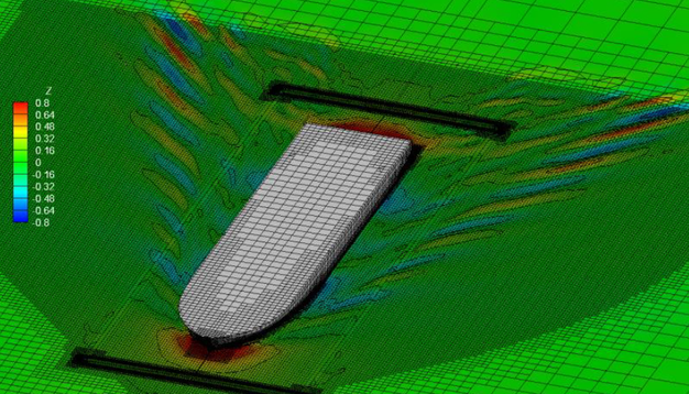 Ship Wave making Resistance
A body moving on an otherwise undisturbed water surface creates a varying pressure field which manifests itself as waves because the pressure at the surface must be constant and equal to atmospheric pressure. From observation when the body moves at a steady speed, the wave pattern seems to remain the same and move with the body. With a ship the energy for creating and maintaining this wave system must be provided by the ship's propulsive system. Put another way, the waves
cause a drag force on the ship which must be opposed by the propulsor if the ship is not to slow down. This drag force is the wave-making resistance.
A submerged body near the surface will also cause waves. It is in this way that a submarine can betray its presence. The waves, and the associated resistance, decrease in magnitude quite quickly with increasing depth of the body until they become negligible at depths a little over half the body length.
The wave pattern
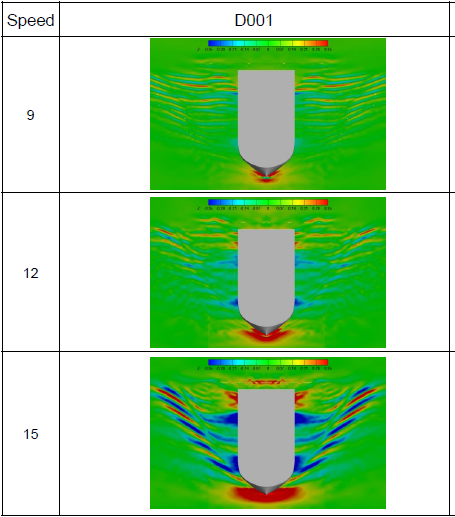
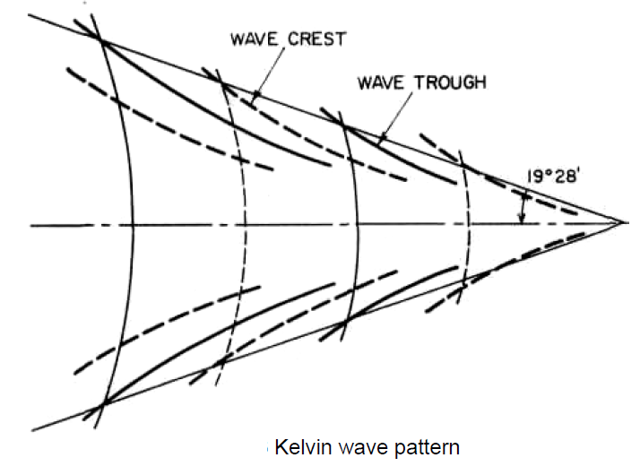
The nature of the wave system created by a ship is similar to that which Kelvin demonstrated for a moving pressure point. Kelvin showed that the wave pattern had two main features: diverging waves on each side of the pressure point with their crests inclined at an angle to the direction of motion and transverse waves with curved crests intersecting the centreline at right angles.
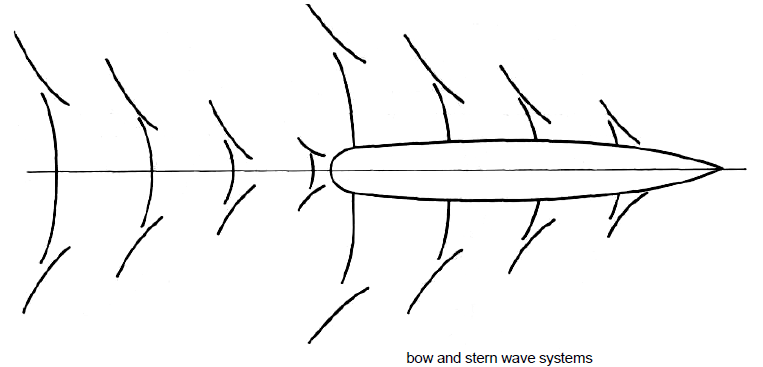
A similar pattern is clear if one looks down on a ship travelling in a calm sea. The diverging waves are readily apparent to anybody on board. The waves move with the ship so the length of the transverse waves must correspond to this speed, that is their length is 2nV1/'g, The pressure field around the ship can be approximated by a moving pressure field close to the bow and a moving suction field near the stern.
Both the forward and after pressure fields create their own wave system. The after field being a suction one creates a trough near the stern instead of a crest as is created at the bow. The angle of the divergent waves to the centreline will not be exactly that of the Kelvin wave field. The maximum crest heights of the divergent waves do lie on a line at an angle to the centreline and the local crests at the maxima are at about twice this angle to the centreline. The stern generated waves are less clear, pardy because they are weaker, but mainly because of the interference they suffer from the bow system.
Interference effects
In addition to the waves created by the bow and stern others may be created by local discontinuities along the ship's length. However the qualitative nature of the interference effects in wave-making resistance are illustrated by considering just the bow and stern systems. The transverse waves from the bow travel aft relative to the ship, reducing in height. When they reach the stern-generated waves they interact with them. If crests of the two systems coincide the resulting wave is of greater magnitude than either because their energies combine. If the crest of one coincides with a trough in the other the resultant energy will be less. Whilst it is convenient to picture two wave systems interacting, in fact the bow wave system modifies the pressure field around the stern so that the waves it generates are altered. Both wave systems are moving with the ship and will have the same lengths. As ship speed increases the wavelengths increase so there will be times when crests combine and others when crest and trough become coincident.
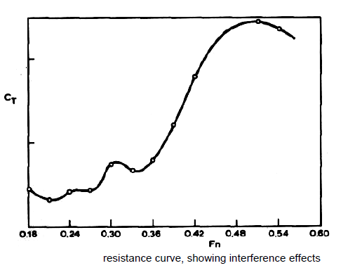
The ship will suffer more or less resistance depending upon whether the two waves augment each other or partially cancel each other out. This leads to a series of humps and hollows in the resistance curve, relative to a smoothly increasing curve, as speed increases.
This effect was shown experimentally by Froude by testing models with varying lengths of parallel middle body but the same forward and after ends.
The troughs will coincide when JVis an odd integer and for even values of N a crest from the bow coincides with the stern trough. The most pronounced hump occurs when N = 1 and this hump is termed the main hump. The hump at N = 3 is often called the prismatic hump as it is greatly affected by the ship's prismatic coefficient.
Scaling wave-making resistance
It has been shown that for geometrically similar bodies moving at corresponding speeds, the wave pattern generated is similar and the wave-making resistance can be taken as proportional to the displacements of the bodies concerned. This assumes that wave-making was unaffected by the viscosity and this is the usual assumption made in studies of this sort. In fact there will be some viscosity but its major effects will be confined to the boundary layer. To a first order then, the effect of viscosity on wave-making resistance can be regarded as that of modifying the hull shape in conformity with the boundary layer addition. These effects are relatively more pronounced at model scale than the full scale which means there is some scale effect on wave making resistance.
The wave-making resistance of a ship is the net fore-and-aft force upon the ship due to the fluid pressures acting normally on all parts of the hull, just as the frictional resistance is the result of the tangential fluid forces. In the case of a deeply submerged body, travelling horizontally at a steady speed far below the surface, no waves are formed, but the normal pressures will vary along the length. In a nonviscous fluid the net fore-and-aft force due to this variation would be zero, as previously noted.
If the body is travelling on or near the surface, however, this variation in pressure causes waves which alter the distribution of pressure over the hull, and the resultant net fore-and-aft force is the wave-making resistance. Over some parts of the hull the changes in pressure will increase the net sternward force, in others decrease it, but the overall effect must be a resistance
of such magnitude that the energy expended in moving the body against it is equal to the energy necessary to maintain the wave system. The wave making resistance depends in large measure on the shapes adopted for the area curve, waterlines and transverse sections, and its determination and the methods by which it can be reduced are among the main goals of the study of ships' resistance. Two paths have been followed in this study—experiments with models in towing tanks and theoretical research into wave-making phenomena. At present, model tests remain the most important tool available for reducing the resistance of specific ship designs, but theory lends invaluable help in interpreting model results and in guiding model research.
Ship Wave Systems
The earliest account of the way in which ship waves are formed is believed to be that due to Lord Kelvin. He considered a single pressure point travelling in a straight line over the surface of the water, sending out waves which combine to form a characteristic pattern. This consists of a system of transverse waves following behind the point, together with a series of divergent waves radiating from the point, the whole pattern being contained within two straight lines starting from the pressure point and making angles of 19 deg 28 min on each side of the line of motion.The heights of successive transverse-wave crests along the middle line behind the pressure point diminish going aft. The waves are curved back some distance out from the centerline and meet the diverging waves in cusps, which are the highest points in the system. The heights of these cusps decrease less rapidly with distance from the point than do those of the transverse waves, so that eventually well astern of the point the divergent waves become the more prominent.
The Kelvin wave pattern illustrates and explains many of the features of the ship-wave system. Near the bow of a ship the most noticeable waves are a series of divergent waves, starting with a large wave at the bow, followed by others arranged on each side along a diagonal line in such a way that each wave is stepped back behind the one in front in echelon and is of quite short length along its crest line.
Between the divergent waves on each side of the ship, transverse waves are formed having their crest lines normal to the direction of motion near the hull, bending back as they approach the divergent-system waves and finally coalescing with them. These transverse waves are most easily seen along the middle portion of a ship or model with parallel body or just behind a ship running at high speed. It is easy to see the general Kelvin pattern in such a bow system.
Similar wave systems are formed at the shoulders, if any, and at the stern, with separate divergent and transverse patterns, but these are not always so clearly distinguishable because of the general disturbance already present from the bow system. Since the wave pattern as a whole moves with the ship, the transverse waves are moving in the same direction as the ship at the same speed V.
The divergent waves will have a different speed along the line normal to their crests . In this case, the component of speed parallel to the line of the ship's motion must be equal to the ship's speed in order to retain the fixed pattern relative to the ship. If the line normal to the crest of a divergent wave makes an angle with the ship's course, the speed in that direction will be V*cos(angle) , and the corresponding wave length.At low speeds, the waves made by the ship are very small, and the resistance is almost wholly viscous in character.
Since the frictional resistance varies at a power of the speed a little less than the square, when the coefficient of total resistance CT = plotted to a base of Froude number Fn (or of at first the value of CT decreases with increase of speed . With further increase in speed, the value of CT begins to increase more and more rapidly, and at Froude numbers approaching 0.45 the resistance may vary at a power of V of 6 or more.
However, this general increase in CT is usually accompanied by a number of humps and hollows in the resistance curve. As the speed of the ship increases, the wave pattern must change, for the length of the waves will increase and the relative positions of their crests and troughs will alter. In this process there will be a succession of speeds when the crests of the two systems reinforce one another, separated by other speeds at which crests and troughs tend to cancel one another.
The former condition leads to higher wave heights, the latter to lower ones, and as the energy of the systems depends upon the square of the wave heights, this means alternating speeds of higher and lower than average resistance. The humps and hollows in the curve are due to these interference effects between the wave systems, and it is obviously good design
practice to ensure whenever possible that the ship will be running under service conditions at a favorable speed. As will be seen later, it is the dependence of these humps and hollows on the Froude number that accounts for the close relationship between economic speeds and ship lengths.
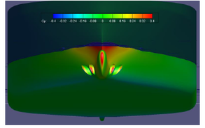
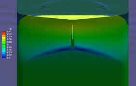
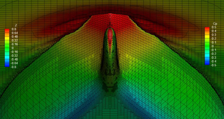
Eggert measured the normal pressure distribution over the ends of a model and plotted resulting pressure contours on a body plan. By integrating the longitudinal components of these pressure forces over the length, he showed that the resulting resistance agreed fairly well with that measured on the model after the estimated frictional resistance had been subtracted. One important point brought out by these experiments is that a large proportion of the wave-making resistance is generated by the upper part of the hull near the still waterline.
Theoretical Calculation of Wave-Making Resistance.
One method is to determine the flow around the hull and hence the normal pressure distribution, and then to integrate the fore-and-aft components of these pressures over the hull surface.
A second method is to calculate the wave pattern generated by the ship at a great distance astern, the wave-making resistance then being measured by the flow of energy necessary to maintain the wave system.
Both methods lead to the same final mathematical expression, and in each case the solution is for a nonviscous and incompressible fluid, so that the ship will experience only wave-making resistance.
Michell obtained the mathematical expression for the flow around a "slender" ship of narrow beam when placed in a uniform stream. From the resultant velocity potential the velocity and pressure distribution over the hull can be obtained, and by integrating the fore and-aft components of the pressure an expression can be derived for the total wave-making resistance.
The theory as developed by Michell is valid only for certain restrictive conditions:
The alternative method in which wave-making resistance is measured by the energy in the wave system, makes use of the idea of sources and sinks. Simulate the flow around different body shapes to find the wave pattern, pressure distribution, and resistance. A "thin" ship, for example, can be simulated by a distribution of sources on the centerline plane of the forebody and of sinks in the afterbody,the sum of their total strength being zero. The re- The velocity potential has the property that the velocity of the flow in any given direction is the partial derivative of with respect to that direction.
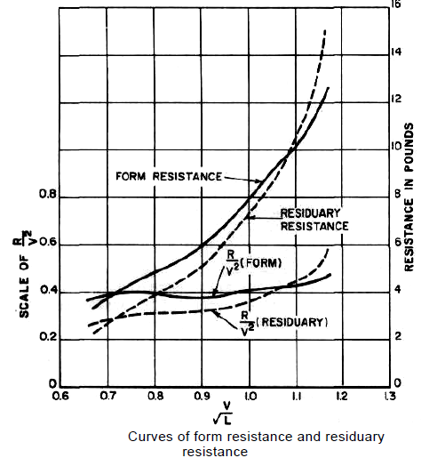
Residuary resistance derived from towing experiments to be everywhere proportional to the slope of the hull surface, this will result in a total strength of zero, and the total velocity potential will be the sum of those due to the individual sources and sinks and the uniform flow. Each source and sink when in motion in a fluid, on or near the surface, gives rise to a wave system, and by summing these up the total system for the ship can be obtained. Havelock by this method found the wave pattern far astern, and from considerations of energy obtained the wave-making resistance.
Professor Inui began with an assumed source-sink distribution, with a view to obtaining better agreement between the measured and calculated wave systems, both of which would refer to the same hull shape. The wave pattern and the wave making resistance were then calculated from the amplitudes of the elementary waves by using Havelock's concept.
Professor Inui tried various distributions of sources and sinks (singularities) by volume over the curved surface, in a horizontal plane and over the vertical middle-line plane. For displacement ships at Froude numbers from 0.1 to 0.35, he found the geometry of the ends to be most important, and these could be represented quite accurately by singularities on the middle-line plane. For higher Froude numbers, the disstriction to a "thin" ship can be removed if the sources and sinks are distributed over the hull surface itself.
A source may be looked upon as a point in a fluid at which new fluid is being continuously introduced, and a sink is the reverse, a point where fluid is being continuously abstracted. The flow out of a source or into a sink will consist of radial straight stream lines. If a source and an equal sink be imagined in a uniform stream flow, the axis of the source and sink being parallel to the flow, the streamlines can be combined , and there will be one completely closed streamline . Since the source and sink are of equal strength, all fluid entering at +s will be removed at — s, and no fluid will flow across streamline, and the space inside this line could be replaced by a solid body.In this way considerably reduced wave-making resistance can be obtained, usually associated with a bulb at the stem and sometimes at the stern also.
Recent developments in wave-making resistance theory can be divided into four main categories. The first concerns applications of linearized potential flow theory, either with empirical corrections to make it more accurate, or uncorrected for special cases where the errors due to linearization are not serious. The second concerns attempts to improve on linearized potential flow theory, by analysis of non-linear effects on the free-surface condition, or by an assessment of the effects of viscosity. Thirdly, attempts have been made to apply wave resistance theory to hull form design. Fourthly there has been an increase in the number of primarily numerical approaches to ship wave resistance estimation.
Determination of pure wave-making resistance from measurements of model wave patterns is more practical. The attempts to improve hull forms using the data of wave pattern measurement combined with linearized theory are particularly interesting.The hull forms of relatively high speed merchant ships have improved because of the application of wave resistance theory.
The development of special types of hull forms for drastically reduced wave making have also been guided to a certain extent by wave resistance theory. One of these is the small waterplane area twin-hull (SWATH) ship.
Interference Effects.
This simple wedge-shaped body illustrates clearly the mechanism of wave interference and its effects upon wave-making resistance. Because of the definite sharp corners at bow, stern, and shoulders, the four free-wave systems have their origins fixed at points along the hull. As speed increases, the wave lengths of each of the four systems increase. Since the primary
crests and troughs are fixed in position, the total wave profile will continuously change in shape with speed as the crests and troughs of the different systems pass through one another. At those speeds where the interference is such that high waves result, the wave making resistance will be high, and vice-versa.
In this simple wedge-shaped form the two principal types of interference are between two systems of the same sign, e.g., bow and stern, or the shoulder systems, and between systems of opposite sign, e.g., bow and forward shoulder. The second type is the most important in this particular case, because the primary hollow of the first shoulder system can coincide with the first trough of the bow system before the latter has been materially reduced by viscous effects.
The mathematical expression for the wave-making resistance Rw is of the form (constant term + 4 oscillating terms) so
that the wave-making resistance coefficient Cw is (constant term + 4 oscillating terms)
The curve is thus made up of a steady increase varying as due to the constant term and four oscillating curves due to the interference between the different free-wave systems . These latter ultimately, at very high speeds, cancel both each other and the steady increase in and there is no further hump beyond that occurring at a value of about 0.45 after which the value of continuously decreases with further increase in speed. However, at these high speeds the hull will sink bodily and change trim so much that entirely new phenomena arise. For more ship-shaped forms, where the waterlines are curved and have no sharp discontinuities, the wave pattern still consists of five components—a symmetrical disturbance and four free-wave systems . Two systems begin with crests, one at the bow and one at the stern, and are due to the change in the angle of the flow at these points. The other two systems, like the shoulder systems in the straight line form, begin with hollows, but are no longer tied to definite points, since the change of slope is now gradual and spread over the whole entrance and run. They commence at the bow and after shoulder, much more gradually than in the case of the wedge-shaped form. The one due to entrance curvature, for example, may be looked upon as a progressive reduction of that due to the bow angle as the slope of the waterline gradually becomes less in going aft.
Up to a Froude number of 0.4 the transverse waves are mainly responsible for the positions of the humps and hollows. Above this speed the contribution from the divergent waves becomes more and more important, and the interference of the transverse waves alone will not correctly determine the position of the higher humps, particularly the last one at Fn = 0.5.
As the ship advances but the water does not, much of the energy given to the water by the bow is carried out laterally and away from the ship. This outward spreading of the energy results in a decrease in the height of each succeeding wave of each system with no appreciable change in wave length.It is clear, however, that its effect is decreasing and would eventually died out.
Wave resistance is generated largely by those parts of the hull near the surface.This suggests that from the point of view of reducing wave making resistance the displacement should be kept as low down as possible. The relatively small effect of the lower part of the hull on the wave systems also means that the wave-making resistance is not unduly sensitive to the midship section shape .
Effects of Viscosity on Wave-Making Resistance.
This effects is to create a boundary layer close to the hull, which separates the latter from the potential-flow pattern with which the theory deals. This layer grows thicker from stem to stern, but outside of it the fluid behaves very much in accordance with the potential flow theory. The direct influence of viscosity on the wave motion is comparatively small, and the indirect effect might possibly be allowed for later by some adjustment of the effective form of the ship.
For a ship model which is unsymmetrical fore and aft, the theoretical wave-making resistance in a nonviscous fluid is the same for both directions of motion, while the measured resistances are different. With the viscosity correction included, the calculated resistance will also be different.
Scale Effect on Wave-Making Resistance
calculated curves of are usually higher than those measured in experiments and also show greater oscillations.
At low speeds errors are negligible, but become important when Fn exceeds 0.35. as evidenced by the sinkage and trim, which increase very rapidly above this speed. In a typical model the actual wave resistance is less than that calculated in a perfect fluid for Froude numbers less than about 0.35. This difference is partly due to viscosity, the effect of which will decrease with increased size, and will increase with scale instead of being constant as assumed in extrapolation work. The effect disappears at low speeds and for values of Fn above 0.45.
The wave making resistance has been measured directly by observing the shape of the wave system astern of the
model and computing its energy and the total viscous drag has been measured by a pitot tube survey behind the model .
At low Froude numbers, less than 0.18, it is difficult to determine CR with any accuracy. At higher speeds, the humps at Fn of 0.25 and 0.32 and the intervening hollow are much exaggerated in the calculated curves, and any advantage expected from designing a ship to run at the "hollow" speed would not be fully achieved in practice . Normal theory overestimates the resistance for full ships with large angles of entrance. Just above a speed of Fn = 0.32 the model becomes subject to increasing sinkage and stern trim, effects which are not taken into account in the calculations.
The last hump in the curve occurs at a Froude number of about 0.5, and here the calculated value of is less than the measured again possibly due to the neglect of sinkage and trim. In all cases the humps and hollows on the measured curves occur at higher values of Fn than those given by theory, by amounts varying from 2 to 8 percent. In other words, the model behaves as though it were longer than its actual length, and this is undoubtedly due mostly to the virtual lenghening of the form due to the viscous boundary layer. At very low speeds, Fn = 0.1, the wave-making resistance varies approximately
as the square of the tangent of the half-angle of entrance, but its total value in terms of RT is very small. At high speeds, with Fn greater than 1.0, the wave-making resistance varies approximately as the square of the displacement,So at very high speeds shape is relatively unimportant, the chief consideration being the displacement carried on a given length.
One method is to determine the flow around the hull and hence the normal pressure distribution, and then to integrate the fore-and-aft components of these pressures over the hull surface.
A second method is to calculate the wave pattern generated by the ship at a great distance astern, the wave-making resistance then being measured by the flow of energy necessary to maintain the wave system.
Both methods lead to the same final mathematical expression, and in each case the solution is for a nonviscous and incompressible fluid, so that the ship will experience only wave-making resistance.
Michell obtained the mathematical expression for the flow around a "slender" ship of narrow beam when placed in a uniform stream. From the resultant velocity potential the velocity and pressure distribution over the hull can be obtained, and by integrating the fore and-aft components of the pressure an expression can be derived for the total wave-making resistance.
The theory as developed by Michell is valid only for certain restrictive conditions:
- The fluid is assumed to be nonviscous and the flow irrotational. Under these circumstances the motion can be specified by a velocity potential ; which in addition must satisfy the necessary boundary conditions.
- The hull is narrow compared with its length, so that the slope of the surface relative to the centerline plane is small.
- The waves generated by the ship have heights small compared with their lengths, so that the squares of the particle velocities can be neglected compared with the ship speed.
- The ship does not experience any sinkage or trim. The boundary conditions to be satisfied by the velocity potential are:
- At all points on the surface of the hull, the normal velocity relative to the hull must be zero.
- The pressure everywhere on the free surface of the water must be constant and equal to the atmospheric pressure.
- To make the problem amenable to existing mathematical methods, Michell assumed that the first boundary condition could be applied to the centerline plane rather than to the actual hull surface, so that the results applied strictly to a vanishingly thin ship, and that the condition of constant pressure could be applied to the original flat, free surface of the water, the distortion of the surface due to the wave pattern being neglected.
The alternative method in which wave-making resistance is measured by the energy in the wave system, makes use of the idea of sources and sinks. Simulate the flow around different body shapes to find the wave pattern, pressure distribution, and resistance. A "thin" ship, for example, can be simulated by a distribution of sources on the centerline plane of the forebody and of sinks in the afterbody,the sum of their total strength being zero. The re- The velocity potential has the property that the velocity of the flow in any given direction is the partial derivative of with respect to that direction.
Residuary resistance derived from towing experiments to be everywhere proportional to the slope of the hull surface, this will result in a total strength of zero, and the total velocity potential will be the sum of those due to the individual sources and sinks and the uniform flow. Each source and sink when in motion in a fluid, on or near the surface, gives rise to a wave system, and by summing these up the total system for the ship can be obtained. Havelock by this method found the wave pattern far astern, and from considerations of energy obtained the wave-making resistance.
Professor Inui began with an assumed source-sink distribution, with a view to obtaining better agreement between the measured and calculated wave systems, both of which would refer to the same hull shape. The wave pattern and the wave making resistance were then calculated from the amplitudes of the elementary waves by using Havelock's concept.
Professor Inui tried various distributions of sources and sinks (singularities) by volume over the curved surface, in a horizontal plane and over the vertical middle-line plane. For displacement ships at Froude numbers from 0.1 to 0.35, he found the geometry of the ends to be most important, and these could be represented quite accurately by singularities on the middle-line plane. For higher Froude numbers, the disstriction to a "thin" ship can be removed if the sources and sinks are distributed over the hull surface itself.
A source may be looked upon as a point in a fluid at which new fluid is being continuously introduced, and a sink is the reverse, a point where fluid is being continuously abstracted. The flow out of a source or into a sink will consist of radial straight stream lines. If a source and an equal sink be imagined in a uniform stream flow, the axis of the source and sink being parallel to the flow, the streamlines can be combined , and there will be one completely closed streamline . Since the source and sink are of equal strength, all fluid entering at +s will be removed at — s, and no fluid will flow across streamline, and the space inside this line could be replaced by a solid body.In this way considerably reduced wave-making resistance can be obtained, usually associated with a bulb at the stem and sometimes at the stern also.
Recent developments in wave-making resistance theory can be divided into four main categories. The first concerns applications of linearized potential flow theory, either with empirical corrections to make it more accurate, or uncorrected for special cases where the errors due to linearization are not serious. The second concerns attempts to improve on linearized potential flow theory, by analysis of non-linear effects on the free-surface condition, or by an assessment of the effects of viscosity. Thirdly, attempts have been made to apply wave resistance theory to hull form design. Fourthly there has been an increase in the number of primarily numerical approaches to ship wave resistance estimation.
Determination of pure wave-making resistance from measurements of model wave patterns is more practical. The attempts to improve hull forms using the data of wave pattern measurement combined with linearized theory are particularly interesting.The hull forms of relatively high speed merchant ships have improved because of the application of wave resistance theory.
The development of special types of hull forms for drastically reduced wave making have also been guided to a certain extent by wave resistance theory. One of these is the small waterplane area twin-hull (SWATH) ship.
Interference Effects.
This simple wedge-shaped body illustrates clearly the mechanism of wave interference and its effects upon wave-making resistance. Because of the definite sharp corners at bow, stern, and shoulders, the four free-wave systems have their origins fixed at points along the hull. As speed increases, the wave lengths of each of the four systems increase. Since the primary
crests and troughs are fixed in position, the total wave profile will continuously change in shape with speed as the crests and troughs of the different systems pass through one another. At those speeds where the interference is such that high waves result, the wave making resistance will be high, and vice-versa.
In this simple wedge-shaped form the two principal types of interference are between two systems of the same sign, e.g., bow and stern, or the shoulder systems, and between systems of opposite sign, e.g., bow and forward shoulder. The second type is the most important in this particular case, because the primary hollow of the first shoulder system can coincide with the first trough of the bow system before the latter has been materially reduced by viscous effects.
The mathematical expression for the wave-making resistance Rw is of the form (constant term + 4 oscillating terms) so
that the wave-making resistance coefficient Cw is (constant term + 4 oscillating terms)
The curve is thus made up of a steady increase varying as due to the constant term and four oscillating curves due to the interference between the different free-wave systems . These latter ultimately, at very high speeds, cancel both each other and the steady increase in and there is no further hump beyond that occurring at a value of about 0.45 after which the value of continuously decreases with further increase in speed. However, at these high speeds the hull will sink bodily and change trim so much that entirely new phenomena arise. For more ship-shaped forms, where the waterlines are curved and have no sharp discontinuities, the wave pattern still consists of five components—a symmetrical disturbance and four free-wave systems . Two systems begin with crests, one at the bow and one at the stern, and are due to the change in the angle of the flow at these points. The other two systems, like the shoulder systems in the straight line form, begin with hollows, but are no longer tied to definite points, since the change of slope is now gradual and spread over the whole entrance and run. They commence at the bow and after shoulder, much more gradually than in the case of the wedge-shaped form. The one due to entrance curvature, for example, may be looked upon as a progressive reduction of that due to the bow angle as the slope of the waterline gradually becomes less in going aft.
Up to a Froude number of 0.4 the transverse waves are mainly responsible for the positions of the humps and hollows. Above this speed the contribution from the divergent waves becomes more and more important, and the interference of the transverse waves alone will not correctly determine the position of the higher humps, particularly the last one at Fn = 0.5.
As the ship advances but the water does not, much of the energy given to the water by the bow is carried out laterally and away from the ship. This outward spreading of the energy results in a decrease in the height of each succeeding wave of each system with no appreciable change in wave length.It is clear, however, that its effect is decreasing and would eventually died out.
Wave resistance is generated largely by those parts of the hull near the surface.This suggests that from the point of view of reducing wave making resistance the displacement should be kept as low down as possible. The relatively small effect of the lower part of the hull on the wave systems also means that the wave-making resistance is not unduly sensitive to the midship section shape .
Effects of Viscosity on Wave-Making Resistance.
This effects is to create a boundary layer close to the hull, which separates the latter from the potential-flow pattern with which the theory deals. This layer grows thicker from stem to stern, but outside of it the fluid behaves very much in accordance with the potential flow theory. The direct influence of viscosity on the wave motion is comparatively small, and the indirect effect might possibly be allowed for later by some adjustment of the effective form of the ship.
For a ship model which is unsymmetrical fore and aft, the theoretical wave-making resistance in a nonviscous fluid is the same for both directions of motion, while the measured resistances are different. With the viscosity correction included, the calculated resistance will also be different.
Scale Effect on Wave-Making Resistance
calculated curves of are usually higher than those measured in experiments and also show greater oscillations.
At low speeds errors are negligible, but become important when Fn exceeds 0.35. as evidenced by the sinkage and trim, which increase very rapidly above this speed. In a typical model the actual wave resistance is less than that calculated in a perfect fluid for Froude numbers less than about 0.35. This difference is partly due to viscosity, the effect of which will decrease with increased size, and will increase with scale instead of being constant as assumed in extrapolation work. The effect disappears at low speeds and for values of Fn above 0.45.
The wave making resistance has been measured directly by observing the shape of the wave system astern of the
model and computing its energy and the total viscous drag has been measured by a pitot tube survey behind the model .
At low Froude numbers, less than 0.18, it is difficult to determine CR with any accuracy. At higher speeds, the humps at Fn of 0.25 and 0.32 and the intervening hollow are much exaggerated in the calculated curves, and any advantage expected from designing a ship to run at the "hollow" speed would not be fully achieved in practice . Normal theory overestimates the resistance for full ships with large angles of entrance. Just above a speed of Fn = 0.32 the model becomes subject to increasing sinkage and stern trim, effects which are not taken into account in the calculations.
The last hump in the curve occurs at a Froude number of about 0.5, and here the calculated value of is less than the measured again possibly due to the neglect of sinkage and trim. In all cases the humps and hollows on the measured curves occur at higher values of Fn than those given by theory, by amounts varying from 2 to 8 percent. In other words, the model behaves as though it were longer than its actual length, and this is undoubtedly due mostly to the virtual lenghening of the form due to the viscous boundary layer. At very low speeds, Fn = 0.1, the wave-making resistance varies approximately
as the square of the tangent of the half-angle of entrance, but its total value in terms of RT is very small. At high speeds, with Fn greater than 1.0, the wave-making resistance varies approximately as the square of the displacement,So at very high speeds shape is relatively unimportant, the chief consideration being the displacement carried on a given length.
