UNDERSTANDING SHIP STABILITY
1.1 EQUILIBRIUM AND STABILITY
In general, a rigid body is considered to be in a state of equilibrium when the resultants of all forces and moments acting on the body are zero. In dealing with static floating body stability, we are interested in that state of equilibrium associated with the floating body upright and at rest in a still liquid. In this case the resultant of all gravity forces (weights) acting downward, and the resultant of the buoyancy forces, acting upward on the body, are of equal magnitude and are applied in the same vertical line.
(A) Stable equilibrium.
If a floating body, initially at equilibrium, is disturbed by an external moment, there will be a change in its angular attitude. If upon removal of the external moment, the body returns to its original position, it is said to have been in stable equilibrium and to have positive stability.
(B) Neutral equilibrium.
If, on the other hand, a floating body that assumes a displaced inclination because of an external moment remains in that displaced position when the external moment is removed, the body is said to have been in neutral equilibrium and has neutral stability. A floating cylindrical homogeneous log would be in neutral equilibrium.
(C) Unstable equilibrium.
If a floating body, displaced from its original angular attitude by an external force, continues to move in the same direction after the force is removed, it is said to have been in unstable equilibrium and was initially unstable.
A ship may be inclined in any direction. Any inclination may be considered as made up of an inclination in the athwartship plane and an inclination in the longitudinal plane. In ship calculations the athwartship inclination, called heel or list, and the longitudinal inclination,
called trim, are usually dealt with separately.
1.2 Weight and Center of Gravity
This topic deals with the forces and moments acting on a ship afloat in calm water, which consist primarily of gravity forces (weights) and buoyancy forces. Therefore, equations are usually developed using displacement weight, W, and component weights, w.
The total weight, or displacement, of a ship can be determined from the draft marks and Curves of Form. The position of the center of gravity may be either calculated or determined experimentally. Both methods are used when dealing with ships. The weight and center of gravity of a ship that has not yet been launched can be established only by a weight estimate, which is a summation of the estimated weights and moments of all the various items that make up the ship.
After the ship is afloat, the weight and center of gravity can be accurately established by an inclining experiment. To calculate the position of the center of gravity of any object, it is assumed to be divided into infinitesimal particles, the moment of each particle calculated by multiplying its weight by its distance from a reference plane, the weights and moments of all the particles added, and the total moment divided by the total weight. The result is the distance of the center of gravity from the reference plane. The location of the center of gravity of a system of weights, such as a ship, may be calculated by multiplying the weight of each component by the distance of its center of gravity from a reference plane, and dividing the total moment of the components by the total weight. The location of the center of gravity is completely determined when its distance from each of three planes has been established.
1.3 Displacement and Center of Buoyancy
Force of buoyancy is equal to the weight of the displaced liquid, and that the resultant of this force acts vertically upward through a point called the center of buoyancy, which is the center of gravity of the displaced liquid. Application of these principles to a ship or submarine makes it possible to evaluate the effect of the hydrostatic pressure acting on the hull and appendages by determining the volume of the ship below the waterline and the centroid of this volume. The submerged volume, when converted to weight or mass of displaced liquid, is called the displacement, W.
1.4 Interaction of Weight and Buoyancy
The attitude of a floating object is determined by the interaction of the forces of weight and buoyancy. If no other forces are acting, it will settle until the force of buoyancy equals the weight, and will rotate until two conditions are satisfied:
(a) The centers of buoyancy B and gravity G are in the same vertical line
(b) Any slight rotation from this position will cause the equal forces of weight and buoyancy to generate a couple tending to move the object back to float on stable equilibrium.
The center of gravity may be either above or below the center of buoyancy.
An exception to the second condition exists when the object is a body of revolution with its center of gravity exactly on the axis of revolution When such an object is rotated to any angle, no moment is produced, since the center of buoyancy is always directly below the center of gravity. It will remain at any angle at which it is placed (neutral equilibrium).
A submerged object that is clear of the bottom can come to rest in only one position. It will rotate until the center of gravity is directly below the center of buoyancy. If its center of gravity coincides with its center of buoyancy, as in the case of a solid body of homogeneous material, the object would remain in any position in which it is placed.
A ship or submarine is designed to float in the upright position. This fact permits the definition of two classes of hydrostatic moments.
Righting moments.
A righting moment exists at any angle of inclination where the forces of weight and buoyancy act to move the ship toward the upright position.
Heeling moments.
A heeling moment exists at any angle of inclination where the forces of weight and buoyancy act to move the ship away from the upright
position. The center of buoyancy of a ship or a surfaced submarine moves with respect to the ship, as the ship is inclined, in a manner that depends upon the shape of the ship in the vicinity of the waterline. The center of buoyancy of a submerged submarine, on the contrary,
does not move with respect to the ship, regardless of the inclination or the shape of the hull, since it is stationary at the center of gravity of the entire submerged volume.
The moment acting on a surface ship can change from a righting moment to a heeling moment, or vice versa, as the ship is inclined, but this cannot occur on a submerged submarine unless there is a shift of the ship's center of gravity.
Lowering of the center of gravity along the ship's centerline increases stability. When a righting moment exists, lowering the center of gravity along the centerline increases the separation of the forces of weight and buoyancy and increases the righting moment. When a heeling moment exists, sufficient lowering of the center of gravity along the centerline would change the heeling moment to a righting moment. Similarly, sufficient lowering of the center of gravity along the centerline could change the initial stability in the upright position from negative to positive.
if the ship's center of gravity were to rise along the centerline, the ship would capsize transversely long before there would be any danger of capsizing longitudinally. However, a surface ship could, theoretically, be made to founder by a downward external force applied toward one end, at a point near the centerline and at a height near or below the center of buoyancy, without capsizing. It is unlikely, however, that an intact ship would encounter a force of the required magnitude.
Surface ships can, and do, founder after extensive flooding as a result of damage at one end. The loss of buoyancy at the damaged end causes the center of buoyancy to move so far toward the opposite end of the ship that subsequent submergence of the damaged
end is not adequate to move the center of buoyancy back to a position in line with the center of gravity, and the ship founders, or capsizes longitudinally.
In the case of a submerged submarine, the center of buoyancy does not move as the submarine is inclined in a fore-and-aft direction. Therefore, capsizing of an intact submerged submarine in the longitudinal direction is possible, and would require very nearly the same moment as would be required to capsize it transversely. If the center of gravity of a submerged submarine were to rise to a position above the center of buoyancy, the direction, longitudinal or transverse, in which it would capsize would depend upon the movement of liquids or loose objects within the ship.
1.5 Upsetting Forces
The magnitude of the upsetting forces, or heeling moments, that may act on a ship determines the magnitude of moment that must be generated by the forces of weight and buoyancy in order to prevent capsizing or excessive heel.External upsetting forces affecting transverse stability may be caused by:
- Beam winds, with or without rolling.
- Lifting of heavy weights over the side.
- High-speed turns.(d) Grounding.
- Strain on mooring lines.
- Towline pull of tugs.
- Internal upsetting forces include:
- Shifting of on-board weights athwartship.
- Entrapped water on deck.
When a ship is exposed to a beam wind, the wind pressure acts on the portion of the ship above the waterline, and the resistance of the water to the ship's lateral motion exerts a force on the opposite side below the waterline. Equilibrium with respect to angle of heel will be reached when:
- The ship is moving to leeward with a speed such that the water resistance equals the wind pressure,and
- The ship has heeled to an angle such that the moment produced by the forces of weight and buoyancy equals the moment developed by the wind pressure and the water pressure.
There are numerous other situations in which external forces can produce heel. A moored ship may be heeled by the combination of strain on the mooring lines and pressure produced by wind or current. Towline strain may produce heeling moments in either the towed or towing ship. In each case, equilibrium would be reached when the center of buoyancy has moved to a point where heeling and righting moments are balanced. In any of the foregoing examples, it is quite possible that equilibrium would not be reached before the ship capsized. It is also possible that equilibrium would not be reached until the angle of heel became so large that water would be shipped through topside openings, and that the weight of this water, running to the low side of the ship, would contribute to capsizing which otherwise would not have occurred. Upsetting forces act to incline a ship in the longitudinal as well as the transverse direction. Shifting of weight saboard in a longitudinal direction can cause large changes in the attitude of the ship because the weights can be moved much farther than in the transverse direction. When very heavy lifts are to be attempted,as in salvage work, they are usually made over the bow or stern, rather than over the side, and large longitudinal inclinations may be involved in these operations.
Stranding at the bow or stern can produce substantial changes in trim. In each case, the principles are the same as previously discussed for transverse inclinations. When a weight is shifted longitudinally,or lifted over the bow or stern, the center of gravity of the ship will move, and the ship will trim until the center of buoyancy is directly below the new position of the center of gravity. If a ship is grounded at the bow or stern, it will assume an attitude such that the moments of weight and buoyancy about the point of contact are equal.
In the case of a submerged submarine, the center of buoyancy is fixed, and a given upsetting moment produces very nearly the same inclination in the longitudinal direction as it does in the transverse direction. The only difference, which is trivial, is due to the effect of liquids aboard which may move to a different extent in the two directions. A submerged submarine, however, is comparatively free from large
upsetting forces. Shifting of the center of gravity as the result of weight changes is carefully avoided. For example, when a torpedo is fired, its weight is immediately replaced by an equal weight of water at the same location.
1.6 Submerged Equilibrium
Before a submarine is submerged, considerable effort has been expended,both in design and operation, to ensure that:
- The weight of the submarine, with its loads and ballast, will be very nearly equal to the weight of the water it will displace when submerged.
- The center of gravity of these weights will be very nearly in the same longitudinal position as the center of buoyancy of the submerged submarine.
- The center of gravity of these weights will be lower than the center of buoyancy of the submerged submarine.
These precautions produce favorable conditions which are described, respectively, as neutral buoyancy,zero trim, and positive stability. A submarine on the surface, with weights adjusted so that the first two conditions will be satisfied upon filling the main ballast tanks, is said to be in diving trim.The effect of this situation is that the submarine,insofar as transverse and longitudinal stability are concerned, acts in the same manner as a pendulum. This imaginary pendulum is supported at the center of buoyancy, has a length equal to the separation of the centers of buoyancy and gravity, and a weight equal to the weight of the submarine.It is not practical to achieve an exact balance of weight and buoyancy, or to bring the center of gravity precisely to the same longitudinal position as the center of buoyancy. It is also not necessary, since minor deviations can be counteracted by the effect of the bow and stern planes when un
TRANSVERSE STABILITY IN SHIPS
Transverse stability largely determines the ship's seaworthiness. Among other things, the location of points G, B and M can determine if a ship, for example, will experience problems in bad weather.
The shipbuilder can influence the location of:
- 'B', through the shape and volume of the hull
- 'M: by the area and shape of the water-plane area.
For every ship B and M are in a fixed position for each particular draft. The crew only has control of G by loading discharging or transferring weight.
Transverse stability can be divided into:
Important for transverse stability are the distances:
The shipbuilder can influence the location of:
- 'B', through the shape and volume of the hull
- 'M: by the area and shape of the water-plane area.
For every ship B and M are in a fixed position for each particular draft. The crew only has control of G by loading discharging or transferring weight.
Transverse stability can be divided into:
- initial stability (angles up to about 5°)
- stability with angles of heel greater than 5°
Important for transverse stability are the distances:
- KM (and if given, BM), indicative for form stability (see table below).
- KG is indicative of weight stability. (must be calculated)
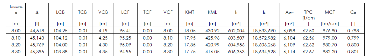
Hydrostatics of a drill ship
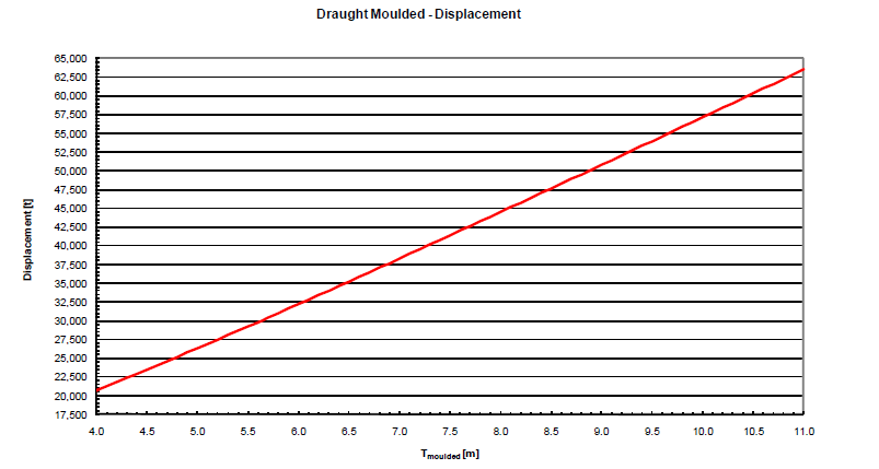
Hydrostatics-Draft vs displacement
|
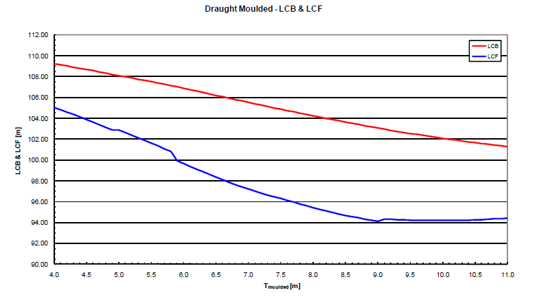
hydrostatics- Draught vs LCB & LCF
|
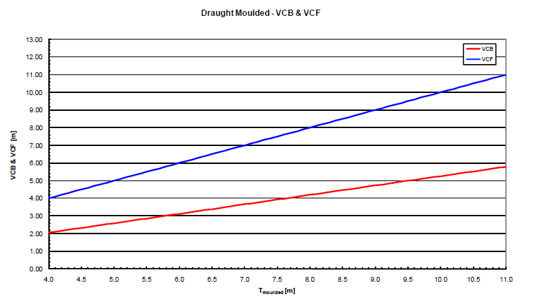
hydrostatics- Draught vs VCB & VCF
|
An extract from the hydrostatic data of drillship are shown above. This clearly shows that with the different draft values of displacement,LCB,LCF,VCB,VCF and many other details changes: This is due to the change o/the surface area and form of the waterline.
3.2 Stability of form and weight
3.2.1 Form stability
If you have a canoe and a rowboat sitting next to each other, the rowboat will appear more stable in the transverse direction than the canoe because the rowboat is beamier. Justifiable, because the wider the vessel, the more stable it is as a rule. Why? As soon as a boat lists slightly, buoyancy shifts to the lower side.
The more beam a vessel has, the more buoyancy (located at B) will shift. The distance over which B moves to the lower sir is proportionate to the square of the beam of the ship.
Transverse stability is largely dependent upon:
- beam,
- draft (prevents the bilge rising out the water),
- Freeboard (prevents the deck edge from going under water).
Definition of form stability.
For a given angle of heel, point B changes position such that a moment (= force) distance) is created. This moment is equal to the up thrust x the distance between work lines of the buoyancy and displacement force. This moment is called the stability moment and works against the angle of heel i.e. tries to return the vessel to initial position of equilibrium.
For a given angle of heel, point B changes position such that a moment (= force) distance) is created. This moment is equal to the up thrust x the distance between work lines of the buoyancy and displacement force. This moment is called the stability moment and works against the angle of heel i.e. tries to return the vessel to initial position of equilibrium.
3.2.2 Weight stability
how can a relatively narrow ship still be stable? As soon as the ship lists, the position of gravity, G, also moves to the lower side
from its original vertical position. However B at the same angle of heel moves more than G moves from its original position.
Then the up thrust return the ship back to her original state of equilibrium. With a relatively narrow ship, B will closer, to G than with a beamy ship.
Afloat, in which there is almost no stability of form, G lies under B. With small list, G moves from the vertical to the is higher side. We are referring now to weight stability.
 Weight Stability in Submarines
Definition of weight stability
With regard to weight stability, only the center of gravity moves from the vertical position. Depending on the location of support (location of the responding force) the body is then in stable, unstable or neutral equilibrium.
Summary
In practice, a ship's seaworthiness is based on both principles of stability, whereby both extremes are also reached.An offshore pontoon that carries its cargo solely on its deck, depends mainly on its form stability, while a submarine depends on its weight stability to remain upright. The submarine and the empty pontoon will experience a short rolling effect and move swiftly,will experience an unpleasant short rolling effect and move stiffly. With other ships, a combination of weight and form stability exists.
3.3 Location of CENTER OF BUOYANCY (B) AND STABILITY
B (Center Of Buoyancy = COB) indicates the location of the resulting buoyancy of the displaced seawater. The location of B is dependent upon the hull's form. B is the volumetric center of the hull and consequently, the center of buoyancy. Buoyancy is equal to the weight (displacement) of the ship. Without the equilibrium of these forces, the ship would capsize.
The resultant (vector) of all upward pressure is always perpendicular to the momentary waterline. This means that the alignment of this vector in calm water is different from that in waves and thus, changes continuously.
The results of the forces that move to G and B position themselves in a line. The ship must, therefore, lie neutral in the water and not move around one of its axes (rolling or pitching, etc.),
The resultant of G is downward and is perpendicular to the horizontal surface area The resultant of B is upward and is perpendicular to the transitory waterline. Both results are equal.
When a ship is sailing in waves, point B continually changes its location. The resulting moment will therefore, continue to attempt to line up B with G.Note: point G remains (with an equivalent weight distribution) a fixed point. If it is unstable the ship will capsize. If the ship loses its equilibrium due to an external force (for example a gust of wind), the distribution of upward force on the hull changes. The outcome is that the resulting buoyancy (B) will move in the direction the movement of B with an increased list. If the ship’s list continues to increase, for whatever reason, then B will also move still further from the vertical plane of symmetry.
Depending on the shape of the hull, B will continue to return to the vertical plane of symmetry as the ship continues to move. Depending on the shape of the superstructure, this will occur as soon as the ship turns 180° (upside down).
3.4 Location of the Metacenter, M AND STABILITY
The importance of M's location to transverse (initial) stability is great. The location ofM depends on the location of B. The location of G in relation to M is mainly decisive for the stability.
Stability can be:
- Positive (G under M)
- Neutral (G at M)
- Unstable (G above M)
|
Here ship heel is 0 degree. So distance between center of buoyancy (B) and Metacenter (M) will depend on water line breadth at that draft. For Higher beam,BM will be large and for narrow beam vessel BM will be smaller
|
As the vessel starts to heel,waterplane area increases. Increased waterplane area helps to increase KN values. So B1M will be more compared to BM.
|
|
As vessel heels further,its deck edge submerged into water and bilge area comes out of water,which will significantly reduce water plane area at the draft. So KN values will start reducing and B1M will also start reducing.
|
As ship heels more,waterplane area further reduces. And distance B1M will reduce further
|
Up to about 5° list and/or trim, it can be assumed that B forms a circle with M as center point. BM is, therefore, a fixed distance. The drawings demonstrate that with an increase in heel, the location of M depends on: the shape of the submerged part of the
ship (thereby, the location of B, which changes continuously in a moving ship) the surface area of the waterline whereby the width of the waterline is the most important factor (this also changes continuously in a moving ship). Consequently, the BM becomes large initiaIIy with an increasing List. If the list further increases, the waterline surface area, decreases along with the BM distance (depending on the draft).
The distance of BM is decisive for amount of righting moment. With larger list, there is a false metacenter N. The value BM for transverse angles is significantly different from M for longitudinally angles with BML being much larger.
3.5 Model data AND STABILITY
The lines plan accurately represents the hull's form. Amongst other lines the water lines are drawn at constant distances from base line to the design waterline. With the Simpson Rules the area of the water plane as well as the area of the ordinates (sections) can be calculated
The following can also be derived from these rules:
- the statically moment of the waterlines in relation to the keel
- the ordinates in relation to the aft perpendicular so that the volume of the hull can be determined.
KB and LCB can be found in this way.
Bonjean curves ROLE IN STABILITY
|
A line representing the area below the water lines at each ordinate gives the possibility to calculate displacements coefficient for a given trim at each ordinate (section). A graph is drawn, whereby the draft can be eadon the vertical axis and the area of the 1 frame on the horizontal axis. The 6 calculated areas are then given and combined in the graph. This graph for all the sections is called the ‘Bonjean Curves’. With the Bonjean curve of each ordinate and the Simpson's Rules: the volume of the hull at each draft and trim can be calculated. The so calculated displacement represents the submerged part of the ship without the shell plating, rudder, propeller etc. The displacement has to be adjusted accordingly. The buoyancy at WL 4 can be found by measuring horizontally the Bonjean curves at the level of waterline 4 for each section. By combining the areas formed below the waterline drawn on these section values represents the buoyancy. In the third figure, the draft is 7 meters, the resulting value for an area of 120. |

Bonjean Curve
|
The Bonjean data appear in table form in the ship's specific stability booklet (hydrostatic particulars).
The following is given for each ordinate and waterline:
Many more sections can be used to determine not only the ship’s displaced volume with each trim but also with each list, preferable with a computer’s assistance. At the same time, it is possible to calculate B for the ship on a series of waves. The accuracy of the calculations rely on the accuracy of the Bonjean curves.
New methods of calculation
The newest methods involve dividing the shell surface in small elements. For each element the hydrostatic pressure is calculated.
To find the sum, by means of the direction and strength of the hydrostatic force on all calculated surface elements, the position of B is determined. The position of B can, in this manner, be calculated for each transitory waterline, as well as in complicated wave systems.
The following is given for each ordinate and waterline:
- The distance from basis to waterline for each ordinate (section). For each water- line, the area of the submerged part of the ordinate.
- The distance from each ordinate to ordinate 0 (is aft perpendicular).
- The statical moment of area in relation to the baseline.
Many more sections can be used to determine not only the ship’s displaced volume with each trim but also with each list, preferable with a computer’s assistance. At the same time, it is possible to calculate B for the ship on a series of waves. The accuracy of the calculations rely on the accuracy of the Bonjean curves.
New methods of calculation
The newest methods involve dividing the shell surface in small elements. For each element the hydrostatic pressure is calculated.
To find the sum, by means of the direction and strength of the hydrostatic force on all calculated surface elements, the position of B is determined. The position of B can, in this manner, be calculated for each transitory waterline, as well as in complicated wave systems.
3.6 Center of gravity 'G' ROLE IN STABILITY
The assumption is that the total weight of the ship (weight of structural parts, machinery, outfit, cargo, fuel, etc.) is concentrated at a point G ( Center of Gravity=COG). The summation and alignment of which, are represented by a vector, the so-called resultant of all weights for the ship. G is the only point that can be directly influenced by the ship's crew. The crew determines where the different weights (cargo, ballast, fuel, supplies) are placed onboard.
In above cargo weight distribution,it has been shown that ship's center of gravity depends highly on distribution height of cargo. As cargo is placed near bottom,G goes down and vice versa as cargo goes up,location of G also goes up.
Vector:
Quantity that indicates magnitude as well as direction. With regard to stability, this means that the vector indicates:
One vector that replaces a number of functioning vectors on the same body without changing the result.
g = center of gravity of component
G = center of gravity of the entire ship.
Amongst other things, the crew decide:
3.6.1 Determination of the location of Center of gravity (G) of Ship
The shipyard estimates the location of G for the 'empty ship'.
The 'light ship weight' is the weight of the ship with only the compulsory inventory onboard 'compulsory equipment': equipment that is part of the completed ship, such as anchors, life-saving apparatus, etc.
The shipyard can fairly accurately determine the light weight of the empty ship based on the materials used. Above the calculations for G (light ship) compulsory inclining experiment has to be performed. The location of G is found from the inclining experiment and adjusted for possible known weights to be added or removed. This is the starting point for the calculation of G for any other loading condition Additionally, the "lightship weight" is determined at the same time as the inclining experiment.
The location of G can be calculated:
3.6.La Law of Moment Equilibrium
The location of G above the keel is determined by all weights of ship and cargo, but also on the position of these weights above the keel (VCJ.
In order to calculate the VCG the following information is necessary:
Moment= force x lever
units: tm x m
For a simple explanation of 'moment: consider a seesaw. A parent exerts a moment in relation to the pivot point of:
80 x 4 = 320 kilogram-meter (kgm)
and the child: 20 x 4 = 80 kgm
Outcome: equilibrium one end of the seesaw is suspended and cannot be moved. The moments are not equal. The moment that both now exert relative to the pivot point, is the same and equilibrium is achieved. The parent exerts a moment relative to the pivot point at 80 x 1 = 80 kgm and the child, the same moment, namely 20 x 4 =80 kgm.
In principle, the same occurs on a ship . If there is equilibrium between all moments to port and starboard there is no list. The axis of rotation is located in the cen- terline plane. This also applies in the longitudinal sense. The ship then turns on the lateral axis through the waterplane Center Of Floatation (COF).
Law of Moment equilibrium:
Total moment of a number of forces (weight) x levers in relation to a fixed point or area is equal to the summation of all the individual moments in relation to the same point or area.
The magnitude of moment exerted on the ship thus dependant upon the:
Quantity that indicates magnitude as well as direction. With regard to stability, this means that the vector indicates:
- a force in tons
- the working direction of this force
One vector that replaces a number of functioning vectors on the same body without changing the result.
g = center of gravity of component
G = center of gravity of the entire ship.
Amongst other things, the crew decide:
- the amount and sequence in which the loaded/ discharged goods are placed
- where they are placed
- which fuel, ballast and drinking water tanks are filled or emptied G is thus, dependent on the magnitude of the ship's weight, and even moreimportant, where it is located.
3.6.1 Determination of the location of Center of gravity (G) of Ship
The shipyard estimates the location of G for the 'empty ship'.
The 'light ship weight' is the weight of the ship with only the compulsory inventory onboard 'compulsory equipment': equipment that is part of the completed ship, such as anchors, life-saving apparatus, etc.
The shipyard can fairly accurately determine the light weight of the empty ship based on the materials used. Above the calculations for G (light ship) compulsory inclining experiment has to be performed. The location of G is found from the inclining experiment and adjusted for possible known weights to be added or removed. This is the starting point for the calculation of G for any other loading condition Additionally, the "lightship weight" is determined at the same time as the inclining experiment.
The location of G can be calculated:
- by the summation of all weight, multiplied by their relative distance from each weight to baseline or aft perpendicular divided by the total weight
- by moving of substantial weights (inclining experiment)
- empirically by measuring the rolling period
3.6.La Law of Moment Equilibrium
The location of G above the keel is determined by all weights of ship and cargo, but also on the position of these weights above the keel (VCJ.
In order to calculate the VCG the following information is necessary:
- displacement and VCG of the empty ship
- the weight of each added load or cargo
- the weight of each added load or cargo
- weight to a point of reference, usually the keel
Moment= force x lever
units: tm x m
For a simple explanation of 'moment: consider a seesaw. A parent exerts a moment in relation to the pivot point of:
80 x 4 = 320 kilogram-meter (kgm)
and the child: 20 x 4 = 80 kgm
Outcome: equilibrium one end of the seesaw is suspended and cannot be moved. The moments are not equal. The moment that both now exert relative to the pivot point, is the same and equilibrium is achieved. The parent exerts a moment relative to the pivot point at 80 x 1 = 80 kgm and the child, the same moment, namely 20 x 4 =80 kgm.
In principle, the same occurs on a ship . If there is equilibrium between all moments to port and starboard there is no list. The axis of rotation is located in the cen- terline plane. This also applies in the longitudinal sense. The ship then turns on the lateral axis through the waterplane Center Of Floatation (COF).
Law of Moment equilibrium:
Total moment of a number of forces (weight) x levers in relation to a fixed point or area is equal to the summation of all the individual moments in relation to the same point or area.
The magnitude of moment exerted on the ship thus dependant upon the:
- magnitude of weight (in tons)
- lever distance (in meters)
Center of gravity Reference
Explanation of different moments that weight (g) exerts on a ship with the points of reference, distances and abbreviations used:
Direction Abbreviation Abbreviation Point of Distance Explained
Momentum explained Reference
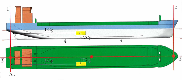
Vertical MH Vertical Moment Keel VCg Vertical
Transverse MT Transverse Moment Centerline TCg
Longitudinal ML Longitudinal Moment Aft perpen LCg Longitudinal
Direction Abbreviation Abbreviation Point of Distance Explained
Momentum explained Reference
Vertical MH Vertical Moment Keel VCg Vertical
Transverse MT Transverse Moment Centerline TCg
Longitudinal ML Longitudinal Moment Aft perpen LCg Longitudinal
 Momentum balance
Points of reference can be:
- aft perpendicular
- fore perpendicular
- amidships
- centerline
- keel (base line).
3. 6.1.c INCLINING TEST
The shipbuilder can estimate the displacement, KG and GM based on the materials (mostly steel) used in building. In order to calculate the correct GM of the empty ship, the ship must undergo an inclining experiment (stability test) to determine KG. The results of the test serve as the basis for all stability calculations. Should the results of the stability test deviate from the ship Builder's calculations, then it could be that the weights of the materials were incorrectly calculated.
The weight of the ‘empty ship’ (= fI. ) must be as accurate as possible. After a substantial conversion, a new inclining experiment can be requested.
During the test:
The test must be conducted multiple times both starboard and portside with consistent outcome to ensure an accurate result.
A known weight (1) is moved transversally across a known distance (2) as a result of which the ship lists. (1) The weight must be so large that:
The shipbuilder can estimate the displacement, KG and GM based on the materials (mostly steel) used in building. In order to calculate the correct GM of the empty ship, the ship must undergo an inclining experiment (stability test) to determine KG. The results of the test serve as the basis for all stability calculations. Should the results of the stability test deviate from the ship Builder's calculations, then it could be that the weights of the materials were incorrectly calculated.
The weight of the ‘empty ship’ (= fI. ) must be as accurate as possible. After a substantial conversion, a new inclining experiment can be requested.
During the test:
- the ship must be free to roll (mooring wires slack, etc.)
- it must be calm with no wind
- no disturbance waves.
The test must be conducted multiple times both starboard and portside with consistent outcome to ensure an accurate result.
A known weight (1) is moved transversally across a known distance (2) as a result of which the ship lists. (1) The weight must be so large that:
- the ship remains within an initial range of stability (max. List 50)
- equal to about 2 % displacement
G’s change of location is indicated in the figure. The ship's list due to relocating the weight is accurately measured. This can be done by means of a plumb line. If a plumb line is used, it is usually suspended in a hold where the weight hangs in a tank of water to stabilize the plumb line.
The result is determined by measuring the distance the pendulum moves on a tape line (QR). In practice,a special instrument is currently used that registers the list in fractions of degrees. After a number of weight moves GM can be calculated.
The result is determined by measuring the distance the pendulum moves on a tape line (QR). In practice,a special instrument is currently used that registers the list in fractions of degrees. After a number of weight moves GM can be calculated.
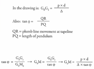
QR = plumb line movement at tapeline
PQ = length of pendulum
The next step is to determine KG. In the hydrostatic tables of the ship, or From the drawing with the hydrostatic curves, for the specific draught T, KM can be found.
KG is then KM - GM
PQ = length of pendulum
The next step is to determine KG. In the hydrostatic tables of the ship, or From the drawing with the hydrostatic curves, for the specific draught T, KM can be found.
KG is then KM - GM
3. 6.1.d Oscillation test
By making the ship roll when in port a rough estimate of GM can be achieved with the formula below.
fx B2T2<p the factor f lies between 0.5 and 0.7. This factor is equal to (2kt)2 ,in which kt is the radius of gyration (see box) of the ship, while rolling.
- B represents the breadth of the ship in meters
- T <p is the oscillation period (time)
Oscillation period: the time, measured in seconds, for a complete rolling from port to starboard and back again to port (or vice versa).
Note:
Radius of gyration
Every ship has a:
This moment consists of a total of all mass gyration moments of each individual mass (Ixx) and the additional mass gyration moment resulting from the water's motion during rolling (mt ).
The following formulation is often used:
g the acceleration gravity in m/ S2.
If the ship's rolling period is measured and the value of GM is known (for example from the stability calculation) then the radius of gyration while rolling can be determined, or the value of kt is known, then the GM can be determined (often used as a means to monitor GM of a ship).
3.6.2 Stiff and tender ship
The formula used with the oscillation test says something important about the rolling period (T) namely: that a relationship exists between the rolling period and GMo. If 'T' is short, (the rolling period short) ,GM (initial stability) is large as is the righting arm. This is referred to as a stiff ship. This usually concerns ships with a heavy cargo (steel or ore) in the lower hold. A ship that is too stiff can be dangerous. The cargo may shift and forces on the ship structure can be to high.
NB: Possibly more ships have been lost by too great a GM than ships with a GM to small. (See IMO recommendations: GM maximum 3% of the breadth).
Besides the difficulties indicated above, rapid rolling in bad weather is also unpleasant for the people on board.
Preventing a ship from being too stiff:
the shipbuilder can design a ship for heavy cargo where the center of gravity of the cargo is relatively high by:
If 'T' is long, (the rolling period long and GM small), the ship is referred to as tender. An increasingly longer rolling period may indicate that the situation onboard may be unsafe and the ship could even capsize.
A typical example of this is the phenomena of icing, freezing of spray in arctic waters. Due to the increase of ice on deck and mast G moves upward and the ship can eventually capsize.
Several advantages of a tender ship:
The condition of a vessel which is too tender, can be improved by discharging weight located above G or loading weight below G. Most ships are generally referred to as 'tender' or 'stiff'. This does not necessarily indicate an unsafe situation. The terms 'too tender' or 'too stiff' are dependant upon so many factors.
By making the ship roll when in port a rough estimate of GM can be achieved with the formula below.
fx B2T2<p the factor f lies between 0.5 and 0.7. This factor is equal to (2kt)2 ,in which kt is the radius of gyration (see box) of the ship, while rolling.
- B represents the breadth of the ship in meters
- T <p is the oscillation period (time)
Oscillation period: the time, measured in seconds, for a complete rolling from port to starboard and back again to port (or vice versa).
Note:
- the rolling action (T) can be achieved, using the ship's crane, by lifting something heavy from shore and afterwards putting it quickly down again as a result of which the ship will roll.
- Conditions: calm water, slack mooring wires, no wind, no waves.
Radius of gyration
Every ship has a:
- mass gyration counter to each motion
- an apparent mass gyration momentum (I",) against rolling (a rotating motion on the x-axis).
This moment consists of a total of all mass gyration moments of each individual mass (Ixx) and the additional mass gyration moment resulting from the water's motion during rolling (mt ).
The following formulation is often used:
- kcp the radius of gyration of the ship while rolling
- the remaining symbols introduce the specific mass of the sea water Ckg/m3) and the displacement (rn"), respectively.
g the acceleration gravity in m/ S2.
If the ship's rolling period is measured and the value of GM is known (for example from the stability calculation) then the radius of gyration while rolling can be determined, or the value of kt is known, then the GM can be determined (often used as a means to monitor GM of a ship).
3.6.2 Stiff and tender ship
The formula used with the oscillation test says something important about the rolling period (T) namely: that a relationship exists between the rolling period and GMo. If 'T' is short, (the rolling period short) ,GM (initial stability) is large as is the righting arm. This is referred to as a stiff ship. This usually concerns ships with a heavy cargo (steel or ore) in the lower hold. A ship that is too stiff can be dangerous. The cargo may shift and forces on the ship structure can be to high.
NB: Possibly more ships have been lost by too great a GM than ships with a GM to small. (See IMO recommendations: GM maximum 3% of the breadth).
Besides the difficulties indicated above, rapid rolling in bad weather is also unpleasant for the people on board.
Preventing a ship from being too stiff:
the shipbuilder can design a ship for heavy cargo where the center of gravity of the cargo is relatively high by:
- a high double bottom
- fortified tween decks (where part of the cargo can be placed)
- fill high tanks with their center of gravity above G and if the maximum displacement is not yet exceeded
- the crew can partly fill tanks in order to create free surface effect. As a result of which G will increase virtually and the ship will be less stiff
If 'T' is long, (the rolling period long and GM small), the ship is referred to as tender. An increasingly longer rolling period may indicate that the situation onboard may be unsafe and the ship could even capsize.
A typical example of this is the phenomena of icing, freezing of spray in arctic waters. Due to the increase of ice on deck and mast G moves upward and the ship can eventually capsize.
Several advantages of a tender ship:
- It is more pleasant for the passengers; therefore, passenger ships are usually tender.
- The load on the structure of a slow-rolling ship is less. The cargo will shift less quickly, the forces on any lashings will be lower.
The condition of a vessel which is too tender, can be improved by discharging weight located above G or loading weight below G. Most ships are generally referred to as 'tender' or 'stiff'. This does not necessarily indicate an unsafe situation. The terms 'too tender' or 'too stiff' are dependant upon so many factors.
Ice formation on decks increases ship's vcg,thus making it more tender and ship becomes prone to capsize.
3.8 Level of Capacity

3.8 The Righting Arm
As seen in the illustration, the moment consists of two equal forces (vectors):
The magnitude of the righting arm (momentum) is the product of:
moment = Displ x GZ
If this formula is further divided, then (see illustration above):
righting moment = Displ x GZ
moment = Displ x GN sin ¢
moment = Displ x (KN - KG) sin ¢
moment = Displ x (KN sin ¢ - KG sin ¢)
From the righting moment it appears that only the crew has influence over the location of G. Namely, the crew can decide how much weight (up to a certain level) can be loaded discharged and where it will be located. crew can only change the remaining factors (Displ, M, KN sin ¢) a little or not at all.
3.8.1 Height of G above the keel
As seen in the illustration, the moment consists of two equal forces (vectors):
- gravity, located at G
- buoyancy, located at B
The magnitude of the righting arm (momentum) is the product of:
- exerted pressure (displacement )
- GZ (lever of statical stability)
moment = Displ x GZ
If this formula is further divided, then (see illustration above):
righting moment = Displ x GZ
moment = Displ x GN sin ¢
moment = Displ x (KN - KG) sin ¢
moment = Displ x (KN sin ¢ - KG sin ¢)
From the righting moment it appears that only the crew has influence over the location of G. Namely, the crew can decide how much weight (up to a certain level) can be loaded discharged and where it will be located. crew can only change the remaining factors (Displ, M, KN sin ¢) a little or not at all.
3.8.1 Height of G above the keel
As stated earlier, the location of G is dependent upon the distribution of weight
on the ship. In each of the illustrations, the added weight (cargo) is placed in a somewhat exaggerated position. The result is that G also shifts to a few extreme positions. It is clear to see that the righting arm changes in direction as well as magnitude. The ship in the drawings lists, due to an external force (a wave, for example). From the illustrations, it appears that G's position is determined to a large extent:
3.8.2 Horizontal displacement of G
on the ship. In each of the illustrations, the added weight (cargo) is placed in a somewhat exaggerated position. The result is that G also shifts to a few extreme positions. It is clear to see that the righting arm changes in direction as well as magnitude. The ship in the drawings lists, due to an external force (a wave, for example). From the illustrations, it appears that G's position is determined to a large extent:
- by the direction of the moment's rotation and thus, the ship
- the magnitude of the righting arm (GZ) and thus, the degree of form stability.
3.8.2 Horizontal displacement of G
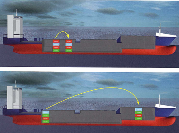
G can move horizontally during loading, discharge or transfer of weight. This causes a short term (a few seconds) listing moment because the buoyancy and gravity vectors no longer line up. As a result, the ship has a list and/or trim. Point B (buoyancy) moves to the lower side.
As soon as the vectors line up again, the lever of the righting moment becomes zero, and the ship remains in position. If the horizontal displacement of G is so great that the buoyancy vector does not come in alignment of the vector of G, then the ship will capsize.
3.8.3 Consequences of incorrect loading
In figures 1 up to 4 is shown a normal stable position, as well as an unstable position:
The situation in figures 3 and 4 is dangerous. G lies above M. The ship is not allowed to go to sea since G must lie a minimal 0.15 meter under M.
As long as the ship is moored, with the hawsers tight, little can happen, but as soon as the ship releases her mooring lines she will list. How far will it list? The breadth of the waterline will increase due to the list. Subsequently M rises. When M lies at G, there is no longer a (turned) arm and the ship will reach maximal list. The only solution is to lower point G. At sea, it is usual to fill the (lower positioned) ballast tanks with seawater.
- moored (hawsers/mooring lines firm)
- unmoored (hawsers loose)
The situation in figures 3 and 4 is dangerous. G lies above M. The ship is not allowed to go to sea since G must lie a minimal 0.15 meter under M.
As long as the ship is moored, with the hawsers tight, little can happen, but as soon as the ship releases her mooring lines she will list. How far will it list? The breadth of the waterline will increase due to the list. Subsequently M rises. When M lies at G, there is no longer a (turned) arm and the ship will reach maximal list. The only solution is to lower point G. At sea, it is usual to fill the (lower positioned) ballast tanks with seawater.
3.9 Curve of Statical stability
In order to illustrate the extension of the righting arm's at each angle, these levers are displayed as a curve, the stability curve (see 3.9.3).
The curve shows the stability of the ship at all heeling angles (usually up to 90°). The curve of the righting arms applies to a specific draft and weight distribution. The righting arm must be sufficiently large at each angle for the ship to right itself various conditions such as bad weather.
The curve must be derived and evaluated: during loading or discharging and before sailing changes of weight distribution during the voyage due to use of fuel and/or drinking water have to be considered.
The calculation and appraisal of the curve can be produced by computer. With each new entry the ships loading computer immediately recalculates the righting arms and thus, the curve. The responsible officer must be thoroughly aware of the basis of this calculation. He/she must know which rules to apply, if the ship's stability is decreasing to such extent that action is required.
As long as the gravity of the ship does not change, the shape of the statical stability curve is determined by the ship's form and the water plane area. For example with a small freeboard or small draft the water plane area can change considerably. The curve is only applicable if the ship lies in calm water. If the ship sails in calm water or waves, the water plane area changes and thus, a continuously changing curve results.
The curve shows:
Cross curves of stability (Stability curves)
For every ship or barge the results of the values of KNsinq as function of the displacement, can be given in table or graph form. Lateral curves of stability are referred to in a graph. These values play an important role in determining GZ. Stability books are not legally required to provide values above 60°. Therefore, a curve with values above 60° is usually not used.
Statical and Dynamical
that is immediately absorbed by that object. "Dynamical" refers to the force exerted on an object that is absorbed gradually by that object.
Statical examples:
This is a statical motion because the swing immediately absorbs the pressure exerted on it. A crane loads a heavy weight on a ship from the quay. While the cargo runner (cable) takes weight, the ship experiences a slowly increasing list. This is a statical motion because the force necessary to hoist the weight is directly absorbed by the ship.
Dynamical examples:
The same swing is pushed higher with considerable force. The swing's gravity cannot absorb the sudden force and shoots upwards. The swing has a dynamic motion in this case.
The same ship has hoisted a heavy weight number of meters. The weight suddenly falls back to the quay and the ship lists to the other side. The ship is in no position to absorb the sudden change in gravity and undergoes a dynamic motion.
Take a ship that lies in equilibrium in calm water without list and trim. With a very small list, the waterlines W oLo and WfLf intersect each other at centerline. Because the ship's form is symmetric in relation to the longitudinal median plane: the increase in displacement to starboard is equal to the decrease in displacement to port. The mean draft remains unchanged.
There is, however, in comparison with a list of 0°, another distribution of displacement over the ship's length. The volume, which results in the fore ship as a result of the list, is not always as great as the volume aft. This is due to the difference in the form of the frame above the waterline fore and aft. Through this new distribution of displacement over the ship's length, there is a new mean draft (which deviates little, however, from the initial draft). At the same time, the initial center of buoyancy 'B' shifts similarly to a list of 0°. A trim moment develops because B and G are no longer lined-up vertically. The ship will trim until this occurs. A new equilibrium is found whereby the ship has trim.
Because the transitory waterline WfLf differs with W oLo' the CO F, with this new waterline, will be different from W oLo'
As a result of the list, the ship has a different:
3.9.2 Determining the righting arm GZ
The righting arm (GZ) can be calculated for a specific heeling angle explained below. GZ can be calculated for different heeling angles from which the GZ curve can be drawn.
Determining GZ (drawing below left):
Abbreviations:
If the righting arms (GZ) are known, a vector is drawn in which vertically: GZ are given in centimeters or meters horizontally: the list angle of the ship for example, from 0° until 60°.
The data of the ship shown here are: If
Draft ==3.90 meters
Displacement = 3500 tons.
KG is known, in this example, 4.9 meters.
Example of calculation KGsin¢:
4.9 meters x sin 10° = 0.851 meter,
4.9 meters x sin 20° = l.676 meters, etc.
To draw the GZ curve's initial path accurately works as follows:
Displacent Heeling angles
merit 5° 10° 20° 30° 40° 50° 60°
4500 0.447 0.894 1.782 2.611 3.453 4.103 4.552
4250 0.445 0.891 1.791 2.630 3.489 4.150 4.552
4000 0.444 0.890 1.793 2.658 3.521 4.192 4.584
3750 0.445 0.892 1.799 2.699 3.551 4.228 4.614
3500 0.458 0.919 1.862 ,2.853 3.672 4.257
3250 0.451 0.905 1.831 2.804 3.626 4.277 4.666 \
3000 0.447 0.896 1.811 2.751 3.586 4.288 4.642
Heeling angle degrees 5° 10° 20° 30° 40° 50° 60°
KNsin¢ meters 0.458 0.919 1.862 2..853 3.672 4.309 4.684
In order to illustrate the extension of the righting arm's at each angle, these levers are displayed as a curve, the stability curve (see 3.9.3).
The curve shows the stability of the ship at all heeling angles (usually up to 90°). The curve of the righting arms applies to a specific draft and weight distribution. The righting arm must be sufficiently large at each angle for the ship to right itself various conditions such as bad weather.
The curve must be derived and evaluated: during loading or discharging and before sailing changes of weight distribution during the voyage due to use of fuel and/or drinking water have to be considered.
The calculation and appraisal of the curve can be produced by computer. With each new entry the ships loading computer immediately recalculates the righting arms and thus, the curve. The responsible officer must be thoroughly aware of the basis of this calculation. He/she must know which rules to apply, if the ship's stability is decreasing to such extent that action is required.
As long as the gravity of the ship does not change, the shape of the statical stability curve is determined by the ship's form and the water plane area. For example with a small freeboard or small draft the water plane area can change considerably. The curve is only applicable if the ship lies in calm water. If the ship sails in calm water or waves, the water plane area changes and thus, a continuously changing curve results.
The curve shows:
- The righting moment or the righting arm at each angle of list
- The energy produced by the righting momentum to resist a list from 0° to any chosen angle.
- Weight (cargo, ballast, etc.) is placed above G
- Weight is discharged under G
- The deck is submerged
- The coaming is submerged
- The bilge rises above water
Cross curves of stability (Stability curves)
For every ship or barge the results of the values of KNsinq as function of the displacement, can be given in table or graph form. Lateral curves of stability are referred to in a graph. These values play an important role in determining GZ. Stability books are not legally required to provide values above 60°. Therefore, a curve with values above 60° is usually not used.
Statical and Dynamical
that is immediately absorbed by that object. "Dynamical" refers to the force exerted on an object that is absorbed gradually by that object.
Statical examples:
This is a statical motion because the swing immediately absorbs the pressure exerted on it. A crane loads a heavy weight on a ship from the quay. While the cargo runner (cable) takes weight, the ship experiences a slowly increasing list. This is a statical motion because the force necessary to hoist the weight is directly absorbed by the ship.
Dynamical examples:
The same swing is pushed higher with considerable force. The swing's gravity cannot absorb the sudden force and shoots upwards. The swing has a dynamic motion in this case.
The same ship has hoisted a heavy weight number of meters. The weight suddenly falls back to the quay and the ship lists to the other side. The ship is in no position to absorb the sudden change in gravity and undergoes a dynamic motion.
Take a ship that lies in equilibrium in calm water without list and trim. With a very small list, the waterlines W oLo and WfLf intersect each other at centerline. Because the ship's form is symmetric in relation to the longitudinal median plane: the increase in displacement to starboard is equal to the decrease in displacement to port. The mean draft remains unchanged.
There is, however, in comparison with a list of 0°, another distribution of displacement over the ship's length. The volume, which results in the fore ship as a result of the list, is not always as great as the volume aft. This is due to the difference in the form of the frame above the waterline fore and aft. Through this new distribution of displacement over the ship's length, there is a new mean draft (which deviates little, however, from the initial draft). At the same time, the initial center of buoyancy 'B' shifts similarly to a list of 0°. A trim moment develops because B and G are no longer lined-up vertically. The ship will trim until this occurs. A new equilibrium is found whereby the ship has trim.
Because the transitory waterline WfLf differs with W oLo' the CO F, with this new waterline, will be different from W oLo'
As a result of the list, the ship has a different:
- Mean draft (however slight)
- Trim (fore and aft draft)
3.9.2 Determining the righting arm GZ
The righting arm (GZ) can be calculated for a specific heeling angle explained below. GZ can be calculated for different heeling angles from which the GZ curve can be drawn.
Determining GZ (drawing below left):
- GZ is equal to PQ
- PQ==KQ-KP
- KQ is equal to KNsin¢.
- KP is equal to KGsin¢
Abbreviations:
- G = Center of Gravity, point of application of the results of the ship's total weight
- ¢ = angle of list
- sino: relationship between the opposite side and the oblique side
- KNsin¢ is calculated by the shipbuilder and can be found in the hydrostatics particulars with the draft amplitude (T) or displacement:
- KG is known; thus KGsin¢ can be calculated.
If the righting arms (GZ) are known, a vector is drawn in which vertically: GZ are given in centimeters or meters horizontally: the list angle of the ship for example, from 0° until 60°.
The data of the ship shown here are: If
Draft ==3.90 meters
Displacement = 3500 tons.
KG is known, in this example, 4.9 meters.
Example of calculation KGsin¢:
4.9 meters x sin 10° = 0.851 meter,
4.9 meters x sin 20° = l.676 meters, etc.
To draw the GZ curve's initial path accurately works as follows:
- place GMo vertically at a heeling angle of 57 (If GMo is negative then it should be drawn below)
- Connect the peak of the vertical with the 0 coordinate
- Draw the curve tangent to the line up to approximately 5°.
Displacent Heeling angles
merit 5° 10° 20° 30° 40° 50° 60°
4500 0.447 0.894 1.782 2.611 3.453 4.103 4.552
4250 0.445 0.891 1.791 2.630 3.489 4.150 4.552
4000 0.444 0.890 1.793 2.658 3.521 4.192 4.584
3750 0.445 0.892 1.799 2.699 3.551 4.228 4.614
3500 0.458 0.919 1.862 ,2.853 3.672 4.257
3250 0.451 0.905 1.831 2.804 3.626 4.277 4.666 \
3000 0.447 0.896 1.811 2.751 3.586 4.288 4.642
Heeling angle degrees 5° 10° 20° 30° 40° 50° 60°
KNsin¢ meters 0.458 0.919 1.862 2..853 3.672 4.309 4.684
3.9.4 Stability regulations
Since it is important to know if the righting arm are sufficiently large, they are placed on a quadrant, with on the horizontal axis the list and on the vertical axis the length of the righting arm. The curve provides an immediate picture of the ship's stability.
Due to its importance, international (IMO) regulations are applied to the area under the GZ curve, the so called Dynamic Stability
(cm.rad). These regulations are set forth in IMO resolutions and MSC publications.
Exceptions to stability criteria
The stability regulations for all ships longer than 24 meters are stated in resolution A 749.
Nevertheless, there are vessels that, because of their construction, nature of their activities or cargo they transport (grain, wood), deviate to such from the normal standard that supplementary regulations have been assigned. Relatively new, are the regulations for containerships longer than 100 meters. With this, the standard regulations, along with a specially adjusted factor for the dimensions of the ship, were tightened. Passenger ships also have supplementary regulations.
Additionally for fishing boats, special purpose ships (factory and expedition ships), supply ships, floating oil rigs, (unsinkable) pontoons, 'dynamically supported craft' such as. Hovercraft, separate regulations are issued.
Regulations applied to 'High speed craft' are published in the 'International Code of Safety for High Speed Craft'. Additionally, there are still no international supplementary rules for sailboats and professionally utilized pleasure craft, only the classification has some regulations.
|
a.1 The area under the righting arm curve (GZ curve) up to 30° angle of heel should not be less than 0,055 metre-radians.
|
a.2 The area under the righting arm curve (GZ curve) should not be less than 0,09 metre-radians up to 40° angle of heel or up to:
|
|
a.3 The angle of flooding (CPf) is less than 40°.
|
|
|
c. The righting arm GZ should be at least 0,20 metres at an angle of heel equal to or greater than 30°.
|
d. The maximum righting arm should occur at an angle of heel preferably exceeding 30° but not less than 25°.
|
e. The initial metacentric height GoMo should not be less than 0,15 meter.
|
The ship with a List. This means that with this List, the righting arm is nil. If the List increases due to rolling, then a righting moment deveLops; if the list decreases, a heeling momentum results. In both cases, the ship will return to its initial list, whereby the lever of the right arm is again nil.
3.9.5 Determining the area under the curve
The area under the curve represents the energy involved in the dynamic stability. In order to calculate the area under the curve, the problem is, that the levers are given in cm or meters on the vertical axis and the angles are given in degrees on the horizontal axis. To find the area below the curve, the heeling angles are also given in terms of distance.
3.9.6 Examples of unacceptable stability curve
|
The curve rises too slowly and does not meet the requirements of regulation a.l. This occurs with ships having either a small KM in relation to KG or a small GM.
|
GMo' (initial stability) is great, the curve rises quickly but has already reached its maximum at an angle of approximately 10°.The curve is not sufficient for regulation d. This can occur with ships that have more beam and little freeboard.
|
This is done to create radians for the number of heeling angle degrees. To give heeling angles in radians, the number of heeling degrees must be divided by 57.3°. When the area below the curve is calculated, centimeter or meter radials are obtained.
The area under the curve can now be calculated in the following ways:
Make a triangle with the same area as the area under the curve.
This is less accurate, but still a good way to obtain a quick impression of the area
(Surface area = h x base x height).
This can be applied to regulations a I, a2 and a3. Make a rectangle of the area.
(Surface area = h x base x height).
This can be applied to regulations bl and b2.
Using the Simpson's Rules
3.9.7 Comparison of ships' forms
When during the design of a ship it is decided to change the main dimensions (draft and beam) but maintaining the same displacement and KG, this results in different curves of static arms as follows:
3.9.7.a The black curve (ship 1)
The ratio of the centerline's draft beam of a cargo ship is 2: 1 to 3: 1. For the base model drawn here, it is 3: 1. The black curve, shown in the stability curve, has an initial stability GMo of approximately 15 cm, the maximum righting arm, 40 cm and the stability's range, 68°. The curve's point of inflection is at 32°, the point at which the deck is immersed. At that point, the waterline width does not increase further. In this case, the ship meets the minimal stability requirements.
3.9.7.b The green curve (ship 2)
The larger freeboard has a noticeable effect on the curve. The initial stability GMo is the same as the base model; the point of inflection, however, lies further away. In this case, with a 34° list when the bilge rises out of the water.
The maximum righting arm is also larger, approximately 63 cm, but more remarkable
is the increase of the stability's range. Up to a 90° list, the ship still has a positive GZ. The area under the curve, representing dynamical stability, is much greater
3. 9. 7.c The red curve (ship 3)
It can be concluded from the previous chapters, that the ship's beam has a positive effect on form stability. This is immediately apparent in the red curve.
The GMo is now about 96 cm and the ship is more rigid. The maximal lever is 90 cm, but the point of inflection is reached earlier at 26° .
The deck and bilge rise up from the water at nearly the same time. The waterline width decreases more quickly than in the base model. The range of stability is only slightly larger than that of the base model.The dynamical angle of capsizing is now approximately 73° and the area below the curve is much greater. The area beneath the curve of ship 3 is, however, almost the same as that of ship 2 with the larger freeboard.
3.9.7.d Conclusion
For ships with the same displacement and KG, compared to the base model, the following conclusions can now be drawn.
If the ship has a higher freeboard:
Increasing the ship's beam:
The area under the curve can now be calculated in the following ways:
Make a triangle with the same area as the area under the curve.
This is less accurate, but still a good way to obtain a quick impression of the area
(Surface area = h x base x height).
This can be applied to regulations a I, a2 and a3. Make a rectangle of the area.
(Surface area = h x base x height).
This can be applied to regulations bl and b2.
Using the Simpson's Rules
3.9.7 Comparison of ships' forms
When during the design of a ship it is decided to change the main dimensions (draft and beam) but maintaining the same displacement and KG, this results in different curves of static arms as follows:
3.9.7.a The black curve (ship 1)
The ratio of the centerline's draft beam of a cargo ship is 2: 1 to 3: 1. For the base model drawn here, it is 3: 1. The black curve, shown in the stability curve, has an initial stability GMo of approximately 15 cm, the maximum righting arm, 40 cm and the stability's range, 68°. The curve's point of inflection is at 32°, the point at which the deck is immersed. At that point, the waterline width does not increase further. In this case, the ship meets the minimal stability requirements.
3.9.7.b The green curve (ship 2)
The larger freeboard has a noticeable effect on the curve. The initial stability GMo is the same as the base model; the point of inflection, however, lies further away. In this case, with a 34° list when the bilge rises out of the water.
The maximum righting arm is also larger, approximately 63 cm, but more remarkable
is the increase of the stability's range. Up to a 90° list, the ship still has a positive GZ. The area under the curve, representing dynamical stability, is much greater
3. 9. 7.c The red curve (ship 3)
It can be concluded from the previous chapters, that the ship's beam has a positive effect on form stability. This is immediately apparent in the red curve.
The GMo is now about 96 cm and the ship is more rigid. The maximal lever is 90 cm, but the point of inflection is reached earlier at 26° .
The deck and bilge rise up from the water at nearly the same time. The waterline width decreases more quickly than in the base model. The range of stability is only slightly larger than that of the base model.The dynamical angle of capsizing is now approximately 73° and the area below the curve is much greater. The area beneath the curve of ship 3 is, however, almost the same as that of ship 2 with the larger freeboard.
3.9.7.d Conclusion
For ships with the same displacement and KG, compared to the base model, the following conclusions can now be drawn.
If the ship has a higher freeboard:
- there is no effect on initial stability
- the range of stability rises considerably
- the area below the curve increases and with this, the dynamical stability is nearly the same as the broader ship it can resist a greater heeling momentum than the base model the effect in swells is the same as that of the base model.
Increasing the ship's beam:
- large effect on initial stability
- has a negligible effect on stability range the area beneath the curve increases and with this, the dynamical stability subsequently, it can withstand a much greater statistical heeling moment than the base model. Thus, the larger the beam, the more rigid (stiff) the ship is.
3.9.8 Statical and dynamical stability
The explanation regarding the difference between statical and dynamical stability can be found on page 48.Statical and dynamical stability are further explained in the following examples. The heeling moment is produced by a beam wind.
The following situations are further examined:
3.9.8.a Statical wind pressure
In this example, there is steady wind pressure on the ship. This pressure has built up so slowly that the moment caused by the exerted force is completely absorbed by the righting moment. When the wind pressure has reached its maximal value and remains constant ,there is equilibrium between the moment caused by wind pressure and the hydrostatic righting moment. Consequently ,The ship has a constant list called a statical list, CPs'. This is expressed in the curve by the vertical levers of the wind moment. The stability regulations are based on the static arm values decreasing with a fixed wind lever value over the whole stability range. This result in a substantial decrease of the area below the curve. The statical heeling angle is where the horizontal line intersects the GZ curve.
The magnitude of the energy built up by the ship during rolling relates to the location of the center of buoyancy (B) and the location of G. The location of these two points (B and G) relates to the size of the righting arm. If a ship rolls due to swells, it will make a specific oscillating motion to both sides of the statical heeling angle.That will depend on draft and GM.
To determine wind heeling lever of any ship following information will be required.
3.9.8.a Wind gust (dynamical)
The ship in this example has a list of 0 degrees. If struck by a wind gust of longer duration,The ship is no longer in a state of equilibrium and rolls to starboard. The force from the gust of wind is greater than the ship can immediately absorb. The result is that the list does not remain confined to static equilibrium angle such as in the previous example, but rolls to approximately 25 degrees. It can be seen in the graph that the 'static equilibrium angle is at 15 degree.
To what extent the ship rolls, is wholly dependent upon the size of area beneath the curve,the dynamical stability. Prior to static equilibrium angle, heeling lever are more than righting arm and after this angle righting arms are more than heeling arm.
In the above drawing, the same figures are used as on the previous page. The lever of the wind arm is once again 0.113 meters. The result is that all righting arms are 0.113 meters smaller at each heeling angle. What remains are the reduced righting arms and accompanying leftover areas. The leftover area or remaining dynamical stability is sufficiently large to absorb the excess energy of the gust of wind. In the example above, the remaining area is large enough. The area that the excess energy absorbs is same as area ADE.
By regulation, wind heeling lever shall be assumed constant throughout all heeling angles. So gust wind heeling arm is drawn as straight line.
Summary:
From 0 to 15 degrees the moment caused by the wind is greater than the static stability moment, subsequently:
Ultimately the area of ABC is same as DCE.
The explanation regarding the difference between statical and dynamical stability can be found on page 48.Statical and dynamical stability are further explained in the following examples. The heeling moment is produced by a beam wind.
The following situations are further examined:
- A steady wind pressure (statical). The ship experiences a constant list.
- A gust of wind at 00 list whereby exerted pressure remains the same during the entire rolling period (dynamical).
- A situation such as mentioned in a. where a lateral force caused by a sudden gust of wind is exerted on the ship (dynamical).
3.9.8.a Statical wind pressure
In this example, there is steady wind pressure on the ship. This pressure has built up so slowly that the moment caused by the exerted force is completely absorbed by the righting moment. When the wind pressure has reached its maximal value and remains constant ,there is equilibrium between the moment caused by wind pressure and the hydrostatic righting moment. Consequently ,The ship has a constant list called a statical list, CPs'. This is expressed in the curve by the vertical levers of the wind moment. The stability regulations are based on the static arm values decreasing with a fixed wind lever value over the whole stability range. This result in a substantial decrease of the area below the curve. The statical heeling angle is where the horizontal line intersects the GZ curve.
The magnitude of the energy built up by the ship during rolling relates to the location of the center of buoyancy (B) and the location of G. The location of these two points (B and G) relates to the size of the righting arm. If a ship rolls due to swells, it will make a specific oscillating motion to both sides of the statical heeling angle.That will depend on draft and GM.
To determine wind heeling lever of any ship following information will be required.
- The magnitude of the profile area above the waterline
- The magnitude of the wind-force per m2
- The point of application of the resulting forces on, the profile area above water and profile area below water
3.9.8.a Wind gust (dynamical)
The ship in this example has a list of 0 degrees. If struck by a wind gust of longer duration,The ship is no longer in a state of equilibrium and rolls to starboard. The force from the gust of wind is greater than the ship can immediately absorb. The result is that the list does not remain confined to static equilibrium angle such as in the previous example, but rolls to approximately 25 degrees. It can be seen in the graph that the 'static equilibrium angle is at 15 degree.
To what extent the ship rolls, is wholly dependent upon the size of area beneath the curve,the dynamical stability. Prior to static equilibrium angle, heeling lever are more than righting arm and after this angle righting arms are more than heeling arm.
In the above drawing, the same figures are used as on the previous page. The lever of the wind arm is once again 0.113 meters. The result is that all righting arms are 0.113 meters smaller at each heeling angle. What remains are the reduced righting arms and accompanying leftover areas. The leftover area or remaining dynamical stability is sufficiently large to absorb the excess energy of the gust of wind. In the example above, the remaining area is large enough. The area that the excess energy absorbs is same as area ADE.
By regulation, wind heeling lever shall be assumed constant throughout all heeling angles. So gust wind heeling arm is drawn as straight line.
Summary:
From 0 to 15 degrees the moment caused by the wind is greater than the static stability moment, subsequently:
- An excess of energy is exerted on the ship.
- The ship rolls beyond 15
- The excess energy built up by the wind decreases as the list increases.
- The ship rolls until about 26 degrees, dynamical equilibrium . The excess energy built up by the wind is gone in the case of dynamic equilibrium.
Ultimately the area of ABC is same as DCE.
3.10 List momentum
The ship's center of gravity moves parallel to the transferred weight or expended force. Across a distance of:
GG'= p x a / .6. ---+ with the transfer of weight (p)
GG'= P x a / (.6. + p) ---+ by loading weight (p)
This weight is a force that causes a moment on the ship. This moment can come either from inside the ship or from outside.
Examples of listing moments:
Equilibrium is disturbed in all of the above situations, either:
The result is that the righting arm (GZ) can change. The above-mentioned situations can be hazardous for the ship.
For each list moment, it must be ascertained whether the moment is a:
Examples of static and dynamic:
The examples here show an exaggerated idea of the consequences to the stability curve and thus, to stability, when weight is shifted (with loading, for example).
Observations regarding these situations:
Drawings 1,2 and 3 show respectively:
Drawings 4, 5 and 6 show respectively:
3.10.1 Free liquid correction
Liquid (or a substance that acts like liquid), that can freely move on a ship, can be extremely hazardous. Annually, many ships capsize, resulting in many casualties.
The seriousness of the situation is largely dependent upon:
Liquid in a tank, hold or on deck, is in fact, weight that can move freely. As soon as the ship lists and/or trims, the liquid moves to the low side whereby the righting capacity decreases or even becomes negative. If liquid can move over the full beam of the ship, the effect is maximal. In particular, a dangerous situation can quickly develop on the (auto) deck of a Ro- ro ship. Because water rushes quickly to the low side, a dynamical effect results, and the ship takes more list.
If the liquid is confined in a tank which is less in width than the beam of the ship, the liquid can only move over the width of the tank and the effect is less serious. This is referred to as the 'free liquid effect'. This causes 'list moment' on the ship, the so called free liquid moment. In order to retain equilibrium, the ship must respond with equal stability moment (the lever of the stability moment is equal to the lever of the list moment).
The following terms and abbreviations are used:
The following figures show the cross section of a ship with an exaggerated large double bottom. In each drawing:
The ship's center of gravity moves parallel to the transferred weight or expended force. Across a distance of:
GG'= p x a / .6. ---+ with the transfer of weight (p)
GG'= P x a / (.6. + p) ---+ by loading weight (p)
This weight is a force that causes a moment on the ship. This moment can come either from inside the ship or from outside.
Examples of listing moments:
- Movement of liquids
- Shifting of cargo
- wind moment
- change of wave moment rudder moment
- tugboat (via hawser)
- collision
- paid out gear (e.g. fishing nets)
Equilibrium is disturbed in all of the above situations, either:
- by transfer or loading of weight
- besides gravity and buoyancy, by a third force exerted on the ship.
The result is that the righting arm (GZ) can change. The above-mentioned situations can be hazardous for the ship.
For each list moment, it must be ascertained whether the moment is a:
- statical moment (continuous force)
- dynamical moment
- combination of both.
Examples of static and dynamic:
- A steady wind is static, a gust of wind, dynamic
- slowly shifting grain gives a statical moment
- weight dropped from a crane has a dynamical moment
- a slowly turning rudder is static, but if it turns quickly it can deliver a combination of statical and dynamical moment.
The examples here show an exaggerated idea of the consequences to the stability curve and thus, to stability, when weight is shifted (with loading, for example).
Observations regarding these situations:
- In practice, a similar asymmetric distribution of weight may not occur and definitely not at sea.
- For clarity's sake, G moves parallel to GZ. G usually moves parallel to the displaced weight.
Drawings 1,2 and 3 show respectively:
- A partially loaded ship (1)
- The ship takes a list from external causes. (2)
- The distribution of weight doesn't change; G's position doesn't change. (2)
- B moves to the low side (2)
- A righting arm with lever G oZ (2)
- The list increases (3)
- Because B moves further towards the low side, the lever of the righting arm becomes considerably larger (3)
Drawings 4, 5 and 6 show respectively:
- A 150 ton weight is moved horizontally resulting in an asymmetric distribution of weight (4)
- The center of gravity, G, moves parallel to the displaced weight. The interval 01 G0G1 is, for example, 0.10 meters. (4) The ship takes a list due to the asymmetric distribution of weight
- External cause (5)
- The lever of the righting arm becorng5 smaller with the interval of GoG1. The lever's extent is now G1Z1. (5)
- The list increases (6)
- The lever of the righting arm (G1 Z1) is smaller than in figure 3.
3.10.1 Free liquid correction
Liquid (or a substance that acts like liquid), that can freely move on a ship, can be extremely hazardous. Annually, many ships capsize, resulting in many casualties.
The seriousness of the situation is largely dependent upon:
- The area in which the liquid can freely move
- The amount of liquid (in relation to the ship's weight)
- The height above the keel where the liquid is placed (Kg)
Liquid in a tank, hold or on deck, is in fact, weight that can move freely. As soon as the ship lists and/or trims, the liquid moves to the low side whereby the righting capacity decreases or even becomes negative. If liquid can move over the full beam of the ship, the effect is maximal. In particular, a dangerous situation can quickly develop on the (auto) deck of a Ro- ro ship. Because water rushes quickly to the low side, a dynamical effect results, and the ship takes more list.
If the liquid is confined in a tank which is less in width than the beam of the ship, the liquid can only move over the width of the tank and the effect is less serious. This is referred to as the 'free liquid effect'. This causes 'list moment' on the ship, the so called free liquid moment. In order to retain equilibrium, the ship must respond with equal stability moment (the lever of the stability moment is equal to the lever of the list moment).
The following terms and abbreviations are used:
- free surface correction (FSC)
- free surface moment (FSM).
- Shifting of liquid (weight), affects the center of gravity G, which then moves away from the centerline. Subsequently the righting arm decreases by G0G1, The righting capacity is thus, reduced.
- As soon as the decline of the lever (GoG1) becomes greater than the maximum righting arms (GZ), the ship will capsize.
The following figures show the cross section of a ship with an exaggerated large double bottom. In each drawing:
- The ship's list is caused by an external force, such as a wave
- The water in which the ship lies, is fresh water
- The liquid in the double bottom tank is also fresh water.
The double bottom tank in figure 1 is empty.
- The center of gravity Go remains in the same place.
- The center of buoyancy moves to the low side parallel to ZuZj
- The magnitude of the righting arm = Ll x GoZ
The double bottom tank is completely filled in figure 2.
Comparison with figure 1:
- Increased draft
The center of gravity G is lower due to the increase in weight under G. The lever of the righting arm is now G] Z
- The center of buoyancy moves the same distance
- The magnitude of the righting arm = Ll x G] Z
Comparison with figure 1:
- Increased draft
The center of gravity G is lower due to the increase in weight under G. The lever of the righting arm is now G] Z
- The center of buoyancy moves the same distance
- The magnitude of the righting arm = Ll x G] Z
The double bottom tank is half full in figure 3.
The liquid flows to the low side. G moves Parallel to line Z II Z. due to the transfer of weight. The result is:
- The magnitude of the righting arm is diminished by approximately GoG1
The righting arm is now G1Z: the resulting lever.
A force can be moved over its own vector. G1 is transferred virtually along its own vector and is virtually located in point G' at now virtually decreased by GoG'.The remaining initial stability is MaG'.
The distance GoG' can be calculated as follows: 12 x Ll .As presented in chapter 3.7, a box-shaped body: =1
t is the surface moment of inertia expressed in m" (Lt x B/). In the hydrostatic data, GoG' is generally noted in rn",
To be expressed as moment (mt), it must be multiplied by the density (p) of the liquid in the tank or divided by the stowage factor.
Remarks:
- The formula can only be applied to a rectangular tank. Since most holds are not rectangular, this formula only gives an approximation.
- Density plays a small role, namely:
- the contents of the tank must be multiplied by p (t/m3) of the transferred liquid
- ship displacement must be multiplied by p (tl m-) of the seawater.
aLegend:
L, = length of tank
B, = breadth of tank
V = ship displacement in rn" Ll = displacement in tons
In figure 4, a lateral bulkhead has been placed in the same double bottom tank, creating 2 similar tanks, in which the breadth is equal to half the width of the whole tank. Both tanks are half full.
By this intervention, the reduction of MoGo (GoG') will be considerable, namely,4 of the original decrease.
The evidence of this is as follows:
There are now 2 tanks, thus 2 corrections
GoG:
However, the tank is halved in breadth, thus B is a 12B.
The breadth is calculated to the 3ed power, thus 12B x 12B x 12B = Ys B3.
The correction per tank is now Ys smaller.
However, there are 2 tanks, thus the total correction is 2 x Ys = \4 of GoG:
If 2 partitions are inserted in the double bottom tank, (creating 3 tanks) then the correction is ';.th of GoG'.
As should be evident, the effect of free flowing water on decks/holds of a Ro- Ro IA
ship can have serious consequences. This is also because on these ships, liquid is then found at a relatively high level.
Example:
Suppose there is a fire on one of the highest auto decks of a Ro-ro ship. By means of an automatic sprinkler system, water spreads on the auto deck. If the water isn't drained quickly enough (for example, with a clogged drain), it will ultimately flow to one side. In this case, the heeling moment will be greater than the righting moment.
(GZmax xzs).
As a result, another force caused by water flowing to one side, develops.
The solution is to install transverse and/or longitudinal bulkheads. However, the placing of these can interfere with trucks being driven on or off the ship.
The problem is also applicable to multi- purpose and heavy load carriers.
On multi-purpose ships, the law requires a (minimum) number of transverse bulk- heads in order to, among other things, reduce the 'free liquid problem'. The dis- advantage is that these bulkheads impede flexible loading and unloading.
Free-flowing water in the lower hold is not as disastrous as water found in higher
holds.
Example:
The effect of free liquid in a large hold, is clarified in the following drawings:
drawings 1: 10 em fresh water stands in
the hold
drawings 3: idem example 2, the hold is now split in 2 compartments by a longitudinal bulkhead.
Displacement (hold not yet filled with water): 1100 tons
The illustrations and curves exemplify real situations.
A dry cargo ship with measurements of:
L = 85.00 meters B = 11.80 meters TswTIme=r 4.95 meters
Displacement (summer) = 4300 tons
Dimensions of hold =
The amount of rn' fresh water in the hold of 1A is:
63 m. x 9.5 m. x 0.10 m. = 60 m ', equal to 60 tons.
In drawing 1B, 60 tons of water has moved to port, a distance of approximately half of the
hold's breadth (9.5 /2)
The center of gravity G moves parallel to the transferred water at a distance of GOG2.
The decrease in the righting arm is already worked out in curve 1D.
Conclusion: the ship takes (WIth 10 ern water 111 the hold) a [ist of 5.5 , a negative 1I11t stability and a smaller area under the curve.
3.10.2 Heavy lift
The use of 'heavy lift' is relative.
What is heavy for one type of ship, may not be for another ship. This chapter deals with ships that load or unload heavy cargo with their own gear.
Heavy cargo can roughly be classified as follows:
_ 'easy heavy lift': pieces from 50 to about
250 tons
_ 'medium heavy lift': pieces from 250 to approximately 1000 tons
_ 'difficult heavy lift': pieces above 1000
tons.
The handling of heavy cargo must always be carried out with the required caution in connection with the risks incurred. Loading, discharging and the voyage itself, require extensive preparation, especially with regard to ship's strength and stability. Also securing of the cargo needs to be looked at in advance.
Multi-purpose ships, normally have two cranes up to 120 tons per crane lifting ca- pacity, which, when working in tandem, can lift pieces of240 tons.
Special designed 'heavy cargo' ships can be fitted with tWOcranes of 1200 tons each. The modern cranes are wireless (remote) controlled from a person on deck or even ashore, close to the piece of cargo.
During the actual cargo operation, i.e. the loading or unloading of one (heavy) parcel,
the intention is to limit a maximum list at
2°.
A larger list is not advised, as the cranes aredesigned to work upright. When working
! I under an angle, stresses in the construction may occur, which are not foreseen.
Also, if the vessel has a larger list, the risk
exists that the cargo moves sideways when coming free from its rest. The moment the cargo is free of the deck, for the ship as a system, its center of gravity moves imme- diately from the original location at rest,in this case the ranktop, to the location of suspension, in this case the top of the crane jib. When at that moment the ship has a list, this list may increase, and the situation is out of control
moment of lift-off. It is therefore of ut- most importance that before the actual hoisting starts, the 'hook' is vertically above the center of gravity of the parcel.
During the tightening of the slings this can be controlled, and adjusted if necessary.
As soon as the winch of the loading gear rums, and the heavy load is lifted off the ship, quay or lighter, the weight will be at the top of the crane's arm.
During the turning, peaking and/or slack- ening of the crane, G will change position continually. As soon as the load is lifted, G will move in the direction of the loading gear's hoist point across a distance equal
to:
pxa
L1
The stability can be improved by tempo- rarily increasing the waterline by utilizing a pontoon at the waterline level firmly at- tached to the ship. This increases the wa- terline width, and so the height of M
Often a tween deck pontoon hatch cover is provided with special attachment devices. The ships shell has attachments at various levels,depending of the draft at the time of cargohandling.
During slewing and topping of the crane,
the position of G will change continuously. The ships list has to be kept under control DY pumping ballastwater.
The voyage, including loading and unload- ing operations, is calculated once more by the shipping company's specialists. After chat,the entire operation is discussed with the ship's captain. The captain is ultimately responsible for the ship's safety.
The list is determined as follows:
GM=pxa/L1x tan <p
It can also be written as:
tan cp =pxa/L1xGM
If the value of tan cp is known, the list cp can be determined.
The formula includes:p:
a:
Ll:
the cargo's weight
the (maximal) distance of the crane's hoist point in relation to the centerline.
the cargo's weight including the heavy load
the interval between G and M
NB·. theessiituauon ponraye d in the first set ofdr aw.mgs is only an example.
In. practice, the list will increase no more than about 2°.
When a heavy cargo weight
has to be lifted from the quay, the slings are tightened first, making sure the hook is vertically above the center of gravity of the weight. The cargo is then lifted by chang- ing the ballast condition of the ship. When the cargo is lifted off the quay and trans- ferred to the ship's hold, bal- last has to be adjusted con- tinuously during the transfer
to keep the ship upright.
Lifting by pumping ballast prevents the ships cargo from bouncing and/or slip- ping when listing to the op- posite side or standing on end, paired with dynamical forces and acceleration, with all inherent damage.
3.10.3 Bulk cargo
3.10.3a General
and flow to the low side on a tilted surface.
and also after settlement (see d), remain
iscould be built that won't crumble. If too much water is added to the wet sand, then it will collapse.Various bulk cargos crashing around in a hold will behave in roughly the same man- ner. This chapter concerns grain and its ef-
3.10.3b Behavior of grain in a hold
Loose grain acts more or less like a liquid.
If a hold or a number of holds are partially
I filled with grain, it has the same effect as a free liquid surface (see chapter 3.10.1).
The grain shifts to one side causing a haz-
extreme case, the ship could capsize. There
I ardous situation onboard and in the most
is also the problem of settling of the cargo.
I For example, if ground coffee is poured into a can, it has a specific volume.
I If the can is struck on the table a few times,
the volume decreases through settling.
Grain refers to all agricultural prod- ucts having the same characteristics, such as wheat, corn, oats, rye, barley, rice, dried peas and beans, seeds and other derivatives with the same quali- ties.
The same occurs with grain in the hold. Due to vibrations and movement of the ship, the grain cargo settles and the volume decreases, but of course, the weight remains the same.
The center of gravity of the grain in the hold will drop somewhat.
Every ship is required to carry a book con- taining a number of specific cargo condi- tions. The book is one of the obligatory certificates and other particulars on board. Amongst other conditions it contains reg- ulations for a grain cargo.
When these regulations are fullfilled the ship may load a grain cargo. The ship then meets the requirements laid out in the IMO 'International Grain Code: (MSC.23(59) ).
3.10.3c loading the holds
If the holds are entirely filled with more or less full, the grain will not shift. It and also after settlement (see d), remain
In practice, the problem often is that the amount of grain to be transported, is not
sufficient to fill the entire hold.Additional bulkheads and 'tween decks keep the grain in place.Once the grain is loaded, the stowage fac- tor provided by the shipper may cause ad-ditional problems (see section 2.9). Theume of space it occupies.
Example:
A specific stowage factor is provided for a
cargo of grain. During loading it appears smaller than indicated: the quantity of
grain is delivered as per contract but the
stated volume is smaller.
Subsequently, the specified hold can't be completely filled and there is space for the grain to move with the afore mentioned stability concequences.
A possible solution is to load additional grain. However, it will not be feasible if the ship has already reached its maximum draft.
3.10.3d The position of G after the grain has shifted
It can be seen in the drawing that G moves parallel to line ZlZ2 as the grain shifts. For clarification purposes, the angle at which the grain has shifted, as well as the position of B, en G] is exaggerated.
Suppose the grain has shifted. What are the consequences for stability? Actually, the weight moves from port to starboard (or vice versa) as described in the previous chapters. The center of gravity G moves
parallel to the movement
a distance equal to:
pxa
p = weight of the grain
a = the distance over which the grain shifts
f1 = displacement
GoG] = volume x a
(m3/t) x t mJ '
How are the various data determined
calculated:
f1: the displacement of the ship includ- ing the grain to be loaded.
- The ship's management obtains the stowage factor (m3/ton or ft3/ton) of the grain from the shipper
The shipbuilder calculates the maxi-'volumetric heeling moment' expressed in rn", This
is to be looked
up in the
grain data.
the level area of the grain is lowered and
tance:
GOGI must be multiplied with factor 'K'
due to settling of the grain. As it settles,
the grain moves laterally over a greater dis-
K = l.00 ---+ completely filled hold as- suming that the center of gravity is equal to the volumetric center of gravity
- K = l.06 ---+ completely filled hold with
below deck holds partially filled.
- K = 1.12 ---+ partially filled hold
After the grain has shifted, a new G is found (G I) and the new lever of the right·
ing arm can be determined (GIZI). This can be figured out by reducing the lever of
the original arm (GoZo) with: (GoG I x cosine heeling angle). Formulated as:
GIZI = GOGI x cos]
3.10.3e Testing the conditions
The table with the grain data onboard ship can quickly indicate whether the ship meets the requirements for the transport of
grain.
The table maximum allowable grain heeling
moment, is used to test the maximal allow'
able heeling moment against the calculated
heeling moment.
Arguments: VCG and displacement.
Note: this concerns the heeling moment (mt) of the cargo. The volumetric heeling moment (rn") must then be divided by the stowage factor (m3 It).
The above requirements stricter than the standard crit
are eria
NB: Ore, in general, does not shift as quickly as grain.
However,if the top layer df one of G
the in between layers contains too much moisture, there is a change ofshifting.
Asore is much heavier than grain the consequences for the ship can be worse.
3.10.4 Effect of wind on the ship
I' General
Wind force:
_ causes waves that, depending on their
size have effect on the ship's motion,
_ causes (extra) heeling depending on:
• the ship's profile area above water
• wind direction and velocity
These factors have an effect on the stability and are discussed in this chapter.
The following stability calculations are provided by the IMO, aruong others:
_ Wind pressure coming from abeam.
_ The wind's effect is determined by the profile area above the waterline. This depends upon:
• the mean draft
• if applicable deck cargo such as containers or project cargo
3.10.4.a Statical forces
\1
If the ship experiences steady wind pressure such as trade winds, it will take a small list. This list originates from the equilibrium between the lever caused by wind and righting arm. (See section 3.9.8 also.)
3.10.4.b Dynamical forces
The rules contain extra requirements re-
garding a rolling ship which undergoes wind gust oflonger duration.
The gust of wind is considered a dynamical force since the ship is unable to absorb the force immediately.
This situation has an effect on the magni-
tude of the (remaining) lever of the right- ing arm and thus, on the curve (see section
3.9, 'Statical and Dynamical').
3.10.4.( Rolling amplitude (¢J
The rolling amplitude (¢) is a continu- ous motion of the ship as a result of waves around a point of equilibrium (¢). The rolling amplitude is, among other things, dependant upon the form of the submerged hull, the size of bilge keel(s) and GM.
Two examples where it is assumed that ¢a is 10°:
If there is no transverse moment (point of equilibrium ¢s is 0°), the ship will roll in swells from 10° to port to 10° to star-
board.
If transverse moment exists and the ship
takes a static list (¢), of about 5° to port, the ship will roll from 15° to port to 5° to starboard in swells.
The rolling period/time (also determined for the extent of ¢), is the time needed for a complete rolling from port to starboard
and back to port.
This can give an indication of the initial stability (GMo)'
3.10.4.d Determining maximum heel after a wind gust (¢J
(See drawing on the following page).
The curve to port is reversed (mirror im- age), so that the heel ¢c can be determined simply.
This works as follows:
a. The ship experiences continues trans- verse wind pressure (heel ¢s = new equi- librium).
b. The ship rolls in swells.
c. The ship reaches its most extreme roll- ing position at a certain moment. From
¢s' the rolling amplitude extends to the high side (to port in the illustration).
d. In this position, the ship experiences a strong gust of wind to starboard.
e. At the same time, the ship begins to roll
f. The forces that make the ship roll back to starboard are a run-down of the forc- es mentioned in a. + d. + e.
g. The ship is unable to roll further than
500 in these circumstances.
3.10.4.e Explanation (for determining ¢J From 10° heel to port to 0° the ship experi- ences the following forces to starboard:
ABC: the energy built up by the ship during rolling from starboard to port
BCDE: the statical wind pressure; thelever of this arm is 0.08 meters
DEFG: wind pressure from gust of
wind
The lever of this arm is 0.08 + (0.08 x
50%) = 0.12 meters
From 0°, the rolling to starboard experi- ences counter-pressure from the excesswa- F
ter pressure (the area below the curve) to
starboard.
D
Subsequently:0.08 meters
at 12° (¢) the lever of the statical wind
pressure equals the righting arm of the
ship
at 15° the combination of both wind le- B
vers (BD + DF) equal the righting arlll
(KH)
_ after KH, both wind levers (BD + DF)
are smaller than the righting arm of the A
ship
_ KLM shows the remaining, the dif-
ference between the area HKMN annHKLN.
staticawl ind lever, for example:
In short, triangle AFK indicates the eneray
b
Il'lhlakinatnI e shiIp to roll to starboard.
e area that the remaining righting arms raetf'iect' must b e surLnCc:'ient 1y large to contain
[[anglewith the size of AFK.
wind lever after gust of wind:
0.08 m + (0.08 x 50%) = 0.12 meters
In this example, KLM (energy directed to port) is equal to AFK. The farthest line of triangle MN cannot pass beyond the 50° angle. The ship then satisfies the wind con- ditions.
If the ship accomplishes this before 50° is
reached, then this angle is considered the
maximum.
3.10.5 Determining a list caused by shifting moment. Summary
3.10.S.a.2 Larger lists (<»>SO) . . Scribanti's formula can be used from 10° to l S", (3.10.3) This formula cannot be used With larger lists.
To find the list for larzer shifting moments, a graphic solution is needed.
The stability curve is the accumulation oflevers of the righting moment (GZ). In the line from 0° to 60°: . ,. .
To draw the lever of the listing moment in the curve, the angle that the ship takes is found at the intersection of the ship s list, influenced
by an asymmetric distribution of weight or a list moment caused by an external forc~. . ., .
A shift moment decreases with the cosine of the heeling angle through an asymmernc distribution of weight.
NB: list moments to starboard move to the top; in list moments to port, they move below.
3.9.S.a.l A small list (<»<SO)
To calculate a small list, the same formula
asymmetric cargo, heavy load
3.10.5.c Heavy load
The list caused by a heavy load placed on one side or a load still hanging from the
can be applied as for the inclination test However, not to calculate GMQ, but in- stead to figure out the expected list caused by the shifting moment. Similar small lists are normally neutralized by counter bal-
last.
Nevertheless, the formula is:
tan cp =
Herewith: p x a = list moment
pxa
And --=GG1
/:,.
This can even be calculated without a cal- culator. For small angles, tan<» = sin<»= ¢ radials apply.
The formula can then be easily applied in:
pxaxS7",3 <»= /:"xGM
Note: An asymmetrically loaded cargo not only
causes a lists, but also has a limited range of
stability.
3.10. 5.b Determining the list caused by the shifting of grain
The shifting lever is calculated by dividing
pxa
/:,.xGMQ
or <»=arctan
3.10. 5.b Determining the list caused by the shifting of grain
The shifting lever is calculated by dividing the volume of shifting moment (VKM) GZ
by the product of stowage factor (sf) and displacement (/:"). That brings the shifting lever to a heeling angle of zero degrees.
VKM Formulated "Yo ITrain =
sfx /:,.
The lever 40° is multiplied by 0.8, the value of cosine 40°.
The curve "Yocoscp can now be drawn in the
Formulated "Y40-grain = 0.8 x "YO-grain
A straight line is drawn through the tip of both levers. The intersection of this line with the curve must then be lower than
12°.
3.10.5.c Heavy load
The list caused by a heavy load placed on one side or a load still hanging from the
The heeling lever is then the product of the cargo's weight (p) and the horizontal dis- tance between G and the cargo's center of gravity (a) divided by the displacement (/:,.)
pxa
Formulated "Yo =--The curve "Yocoscp can now be drawn in the
stability curve.
Or in simplified terms, just as with grain, the lever at 40° list, namely, 0.8"yo-
The point of intersection indicates the list.
Cargo of large ships
3.10. 5.d 'External forces
The law is based on the assumption that the heeling force in the entire range re- mains steady during the wind moment for normal ships. This is done to simplify the calculation and provides extra safety (see
With sailing vessels, the wind lever de- creases with cos2cp (see section 6.1).
The curve "YOCOS2cp is then drawn in the sta- bility curve in order to determine the angle with a specific wind force given a certain sail area. With listing forces that tug boats, can exert on a ship, the lever of the listing moment decreases again with coscp.
3.11 Various topics
3.11.1 KG max
The form, values and range of the stability curve are determined by formula:
GZ(O° - 60°) = KNsinY"- KGsinY", whereby the values for KNsinY'"just as those of KM, are determined by the form of the hulL They are given for the mean draft and trim or displacement in sea water.
For a specific displacement, the maximum KG can be verified so that the conditions pertaining to stability are satisfied. Particularly for ships having no loading and
stability computer onboard, the maximum possible KG is calculated for each displace- ment. These are then checked against all requirements.
Small drafts are indicated at the top of the curve (preferably Y"> 30°, but not smaller than 25°).
KM is large for small drafts, but the bilge
will rise quickly out of the water and the
top will be easily reached.
The wind requirement plays a larger role with smaller drafts than with larger drafts.
If the draft increases, the minimal GM (>O.ISm) or the area under the curve will playa role. To determine which require-KG can be calculated for each draft (dis- placement). These are placed on a chart for small ships.
The displacement is indicated on the hori- zontal axis and the KGmax, on the verti- cal axis. Whether the ship meets all the requirements, can now be seen at a glance. However, it does not indicate why a ship doesn't meet the requirements.
The same calculations are also provided in tables with accompanying stability data.
For each 10 ern difference in draft, themaximum possible KG is indicated for each stability requirement.
Thus for the:
- maximum GZ at Y">30°(req. 1) position of the top of the curve (req. 2) area under the curve up to 30° (req. 3) increase from 30° to 40° (req. 4)
area from 0° - 40° (req. 5)
minimal GMo (req. 6)
wind condition (req. 7).
The last column (Max. VCG) indicates which condition is representative
(always the condition with the smallest
KG).
There may be another column with further trim details and also the maximal value of KG in relation to stability in the case of damage.
The tables show why the ship does not meet the requirements.
Neither of the methods, however, provides information or an indication about statical or dynamical range of stability or the actual position of the top of the curve, as shown in the stability curve.
3.11.2 Calculation of the area under the curve
The area under the stability curve, representing the energy a ship can exert against a mo-
ment caused by a list, can be represented as 2:GZ¢, whereby ¢ is reported in radian.
As long as the curve runs evenly, the calculation of the area can be estimated by regarding the area 0- 30° as a triangle and the area 30-40°, a trapezium
Area 0°_30° is then: 0.5 x (300/5r,3) x GZ30° mrad = 0.262 x GZ30° mrad
Area 30°-40° is then: 0.5(10°/57°,3) x (GZ30° + Gz400) mrad =
0.873 x (GZ30° + GZ400) mrad
For a more accurate calculation of the area, especially if the curve is less regular, such as ships with a low freeboard and a high coaming, Simpson's Rules can be used assuming that the curve is of the second degree. The substantiation of this will not be addressed
here. The resulting area is a reasonably accurate estimate.
The practical application is (see figure):
The curve is divided in a number of equal parts (h) on the X axis.
In this case, 4, resulting in an uneven number of vertical ordinates (Yo-Y 4)'
According to Simpson's Isr rule, the area is now
V3x h x (Yo + 4 *y 1 + 2 x Y 2 + 4 x Y 3 + Y 4)
The calculation of the area under the curve using the 1st rule of Simpson works as fol- lows:
The area from 0°_30°, 0°-40° and the increase from 30°_40° must be calculated There is
one problem in calculating the area 0-30°. Because this part of the curve cannot be divided in an equal number of parts on the X axis, (from which the GZ value is determine an
intermediate step is used.
First, the area 0°-10° has to be calculated and this part of the curve regarded as a triangle
(area shaded in blue).
Next, the area from 10°-30° (in red) has to be calculated; together, they indicate the area
0°_30°.
The area from 0°-40° can be directly figured using Simpson's lsr Rule.
To reduce the area from 0°_30°, an increase from 30°-40° is obtained (in green)
10° is equal to 10°/5r,3 = 0.175 radials
The calculation now includes the following steps: Area 0° _10° = 0.5 x 0.175 x GZ1 = A
Area 10° _ 30° = V3x 0.175 x (GZ1 0° + 4*GZ20° + GZ300) = B
Area 0° - 30° = A + B
Area 0° _40° = V3x 0.175 x (GZO° + 4 x GZlO° + 2 x GZ20° + 4 x GZ30° + GZ400) = C
Increase 30° - 40° = C - (A + B)
3.11.3 Mathematical explanation of the stability curve
The formula to calculate stability levers is
GZ = KNsin)1>- KGsin)1>
KGsin)1>has a pure sine form and is 0 by 0°
and a maximum of 90°.
KNsin)1>however, has no pure sine form be- cause KN is a continually changing value. The form of the curve then is also solely determined by KNsin)1>.
The irregularities are caused by the inter- section of the waterline and hull at differ-
ent angles )1>.
The start of the curve (origin to ca. 3°)
For the range from 0° to ca. 3° the calcula- tion GZ = GM sin()1»is used.
This formula can also be represented by
GZ=GMx)1>
with the angle )1>in radian equal to the
first straight (linear) part of the GZ curve. Thus, the intersecting angle of the curve with the source can also be found by ex- tending GMo at 57°,3.
Scribanti's formula
From ca. 3°, the GZ curve is non-linear and the form can be reasonably well described
by Scribanti 's Formula.
GZ = (GM + 0.5 BM tan2()1») sin()1».
Scribanti's formula applies to ships with straight side walls, so far the deck is not submerged nor the bilge rise out of the wa-
ter.
Scribanti is useful until about a 10° heeling angle for normal ships with straight side walls. Beyond that, so many irregularities play a role, that a straightforward math- ematical equation is no longer possible. For ships with pronounced outward or inward thrusting frames, Scribanti's formula is not recommended as the results are not accu-
rate enough.
Explanation of Scribanti's formula
Basis
_ ship has vertical side walls
the deck edge is not submerged bilge does not rise out of waterFrom the above figure of a.ship with a heeling angle ¢,
GZ<I! = GZ~ + Z~ZcjJ
making use of the displacement rule, the following applies:
f
L
12 y2 tano 23 y tanc dx
_ Vu 23 Y tan<p o
Zcp V
f
12 tan2<p 23
o
y3 dx
Filling in the above, GZ$ = GMsin<j) +Z~ sin ]
results in Scribantis formula
Application of Scribanti:
Suppose a ship has negative initial stability, like the lever of statical stability below.
How large is the heeling angle (cp) if
GZ=O?
GZ" = (GM + ~BMtan2<j) )sin<j) = 0 sino =0 v GM + ~BMtan2<j) = 0
According to Scribanti, GZ = 0:
GZ = 0 if: ,I
<j)= 0 or
From which:
The first solution applies to the upright ship and the second, to the ship with a heeling angle or loll.
Sample calculation:
<ilL _- arctan ~-2-G-- M = ~-2X(-0.1) = M-.2 = 0.2 radialen
BM 4.8 4.8
<ilL = 0.2 radialen x 57.3 graden/radiaal = 11.5 graden
Given GM = -0.1 m and BM = 4.8 m
For a ship with assigned GM and M values,
the ship appears to be unstable (to GM <
0). In flat water, the ship will not capsize, but will turn on its longitudinal axis until it reaches a fixed heeling angle equal to
11°.5.
How high is initial instability then at this
statical heeling angle?
Initial stability in this situation can be de- termined using the following data.
The tangent to the GZ curve at point GZ=O creates an angle with the axis whose tangent is equal to the value of initial in- stability.
This is made visible in the figure as GML•
