SHIP RESISTANCE & PROPULSION CALCULATORS
- RESISTANCE PREDICTION HOLTROP MENNEN METHOD
- RESISTANCE PREDICTION TRAWLER (RIDGELEY-NEVITT)
- RESISTANCE PREDICTION DISPLACEMENT - SEMI PLANNING BOAT ( GROOT )
- PROPELLER POWER AND THRUST COMPARISON FOR ENGINES
- BOAT PROPELLER THRUST AND ENGINE OPTIMIZATION
- PROPULSION SYSTEM DESIGN
- POWER PREDICTION OF BOATS - GERR METHOD
- RESISTANCE PREDICTION OF SYSTEMATIC SERIES OF SEMIPLANING-USNA
- RESISTANCE PREDICTION-FISHER METHOD
- RESISTANCE PREDICTION-SEMIPLANING TRANSOM STERN HULLS (LAHTIHARJU)
- RESISTANCE PREDICTION-HIGH SPEED CRAFT (MERCIER-SAVISTKY)
- RESISTANCE PREDICTION-TRANSOM STERN HULL (FUNG)
- PROPELLER STRENGTH CALCULATION FOR NAVIGATION IN ICE
- B SERIES PROPELLER DESIGN
- B SERIES PROPELLER WEIGHT ESTIMATION
SHIP FRICTIONAL RESISTANCE
SHIP FRICTIONAL RESISTANCE
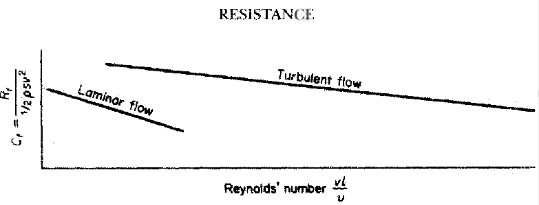
Water is viscous so water particles immediately close to ship hull follow it and move at the speed of the ship speed. At a distance from the hull the water particles are not moving at all. This velocity gradient is highest near to hull. The volume of water which moves with the body is known as the boundary layer. Its thickness is usually defined as the distance from the hull at which the water velocity is 1 per cent of the ship speed.Frictional resistance is associated with Reynolds because of the study he made of flow through pipes. He showed that there are two distinct types of flow. In the first, laminar flow, each fluid particle follows its own streamlined path with no mass transfer between adjacent layers. This flow only occurs at relatively low Reynolds' numbers. At higher numbers the steady flow pattern breaks down and is replaced by a more confused flow pattern called turbulent flow.
Figure : Flow speed variation along the hull
Reynolds showed that different laws of resistance applied to the two flow types. Further, if care was taken to ensure that the fluid entered the mouth of the pipe smoothly the flow started off as laminar but at some distance along the tube changed to turbulent. This occurred at a critical velocity dependent upon the pipe diameter and the fluid viscosity. For different pipe diameters, d, the critical velocity, Vc, was such that Vcd/v was constant. Below the critical velocity, resistance to flow was proportional to the velocity of flow. As velocity increased above the critical value there was an unstable region where the resistance appeared to obey no simple law. At higher velocity again the flow was fully turbulent and resistance became proportional to V raised to the power 1.723.
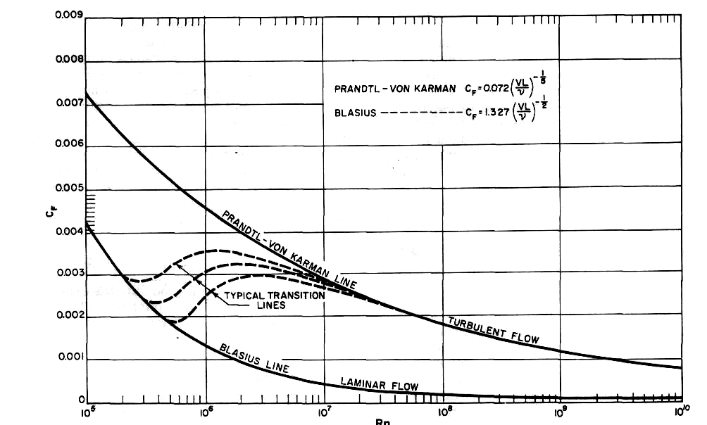
Reynolds' work related to pipes but qualitatively the conclusions are relevant to ships. There are two flow regimes, laminar and turbulent.The change from one to the other depends on the critical Reynolds' number and different resistance laws apply. The critical Reynolds' number at higher numbers is turbulent and resistance is higher.The critical reynolds number at which breakdown of laminar flow occurs depends upon the smoothness of the surface and the initial turbulence present in the fluid. For a smooth flat plate it occurs at a Reynolds' number between 3 X 10⁵ and 106.
In turbulent flow the boundary layer still exists but in this case,besides the molecular friction force there is an interaction due to momentum transfer of fluid masses between adjacent layers. The transition from one type of flow to the other is a matter of stability of flow. At low Reynolds' numbers, disturbances die out and the flow is stable. At the critical value the laminar flow becomes unstable and the slightest disturbance will create turbulence. The critical Reynolds' number for a flat plate is a function of the distance, /, from the leading edge.
Ahead of the point defined by / the flow is laminar. At / transition begins and after a transition region turbulence is fully established. For a flat plate the critical Reynolds' number is about 106. A curved surface is subject to a pressure gradient and this has a marked affect on transition. Where pressure is decreasing transition is delayed.
Even in turbulent flow the fluid particles in contact with the surface are at rest relative to the surface. There exists a very thin laminar sublayer.Although thin, it is important as a body appears smooth if the surface roughness does not project through this sub-layer. Such a body is said to be hydraulically smooth.
The existence of two flow regimes is important for model tests conducted to determine a ship's resistance. If the model is too small it may be running in the region of mixed flow. The ship obviously has turbulent flow over the hull. If the model flow was completely laminar this could be allowed for by calculation. However this is unlikely and the small model would more probably have laminar flow forward turning to turbulent flow at some point along its length. To remove this possibility models are fitted with some form of turbulence stimulation at the bow. This may be a trip wire, a strip of sandpaper or a line of
studs.
Viscosity modifies the flow around the hull,creating build up of pressure around the after end which is predicted for a perfect fluid. This effect leads to what is sometimes termed viscous pressure resistance or form resistance since it is dependent on the ship's form. The streamline flow around the hull will vary in velocity causing local variations in frictional resistance. Where the hull has sudden changes of section they may not be able to follow the lines exactly and the flow 'breaks away'. For instance, this will occur at a transom stern. In breaking away, eddies are formed which absorb energy and thus cause a resistance.
Frictional resistance in new and slow speed ships accounts for 75 to 85 percent of the total resistance. In new and high speed vessels it might go as much as 50 percent of total resistance. Roughness on ship surface considerably increase frictional resistance. Normally corrosion and fouling increase with age of ship,which increases frictional resistance in great extent. As. Frictional resistance is the frictional resistance increases due to these factors,wake factors and propulsive efficiencies are also affected.
Frictional resistance for longer hulls are relatively lower compared to shorter hulls for similar wetted area of hull. Because for longer hulls,water in the aft region moves in the direction of hull thus lowering the relative area in aft region.
Two-dimensional Frictional Resistance
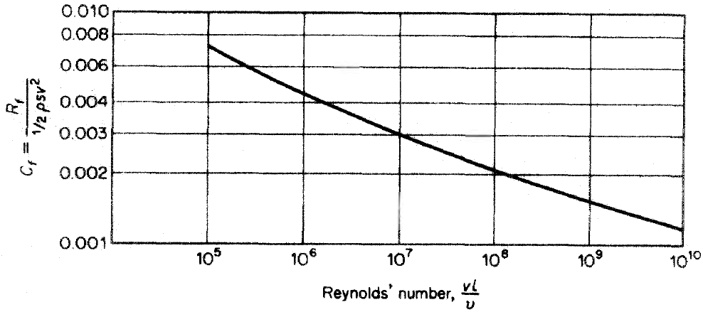
In his experiments,Reynolds found that the laws of resistance exactly corresponded for velocities in the ratio v/D,and when the results were plotted logarithmically.Below the critical velocity the resistance to flow in the pipe varied directly as the speed, while for higher velocities it varied at a power of the speed somewhat less than 2.
Slow speed Laminar flow resistance
At lower velocities,fluid flows in layers and slid over one another at relative speeds,such flows are laminar flows and accounts for lower frictional resistance.
High speed Laminar flow resistance
At higher reynolds number ( VD/v), the laminar flow brakes down, the fluid mixed transversely in eddying motion, and the resistance increased. This flow is called turbulent. Laminar flow became unstable at Reynolds numbers of the order of 4.5 x10⁶, beyond which the resistance coefficients increased rapidly
Resistance R varies For turbulent flow, the value of the resistance coefficient is considerably higher than for laminar flow,and varies as a higher power of the speed.The transition from laminar flow to turbulent flow begins when the Reynolds number reaches a critical value .
Development of Frictional Resistance Formulations
The difference between the ship resistance as deduced from full-scale trials and that predicted from the model depends upon model-ship correlation allowance.
Three-Dimensional Viscous Resistance Formulations.
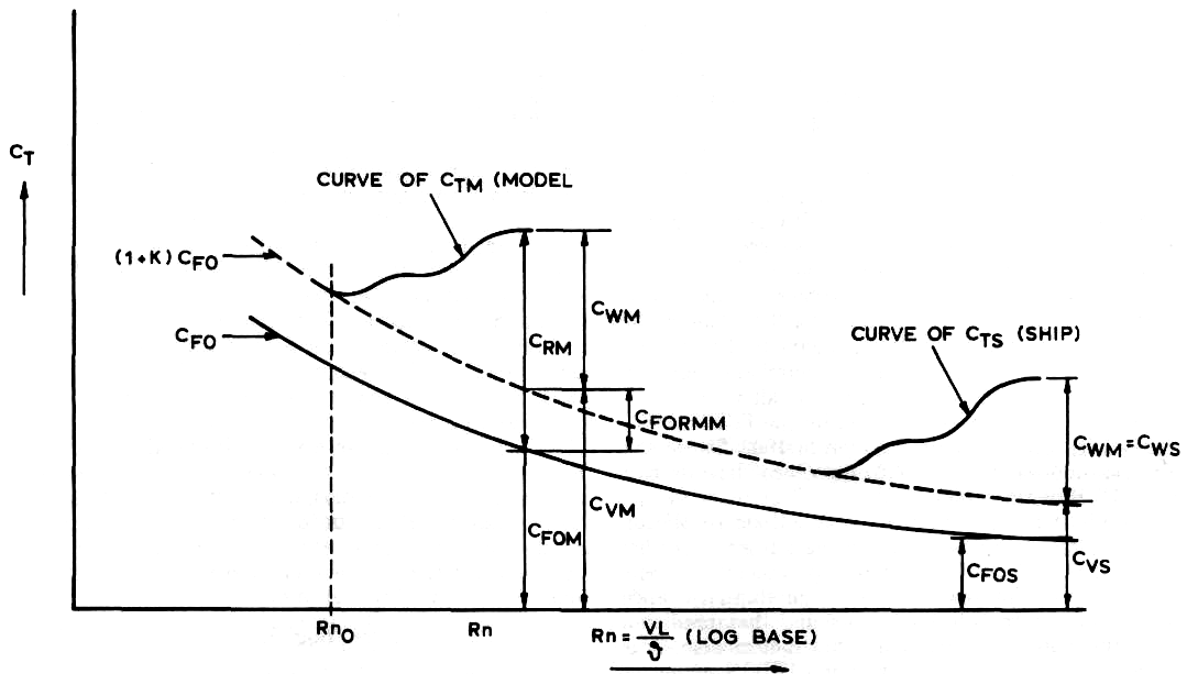
Hughes proposed a new method of extrapolation from model to ship. He assumed that the total model resistance coefficient Ctm could be divided into two parts, Cvm and Cwm, representing the viscous and wave making resistance, respectively. At low Froude numbers, Cwm will become very small, and at a point where wave making can be neglected, the curve of Ctm will become approximately parallel to the two-dimensional friction line.
The value of Ctm at this point can then be identified with the total viscous resistance coefficient Cvm at the same point Rn0.
The form resistance coefficient, due at least in part to the curvature of the hull , is defined by The three-dimensional model viscous resistance for arbitrary Rn can now be written as CVM = (1 + k) CF0 (Rn) where CF0 is the equivalent flat-plate resistance coefficient. The factor k accounts for the three-dimensional form, and is appropriately termed the form factor. The form factor (1 + k) is assumed to be invariant with Rn and the line (1 + A;) is now taken as the extrapolator for the hull form concerned, and the ship curve of can be drawn above the (1 +k) curve at the appropriate values of the Reynolds number.
The three dimensional method gives substantially lower ship predictions and so calls for larger values of the correlation allowance This procedure avoids the negative allowances sometimes found when using the Froude method. It should also be noted that in the case of the Froude method only the slope of the two-dimensional friction line matters while in the case of the form factor approach the vertical position of the line also affects the ship prediction. The choice of the basic line becomes an essential factor in the case of the three-dimensional approach.
The ITTC has recommended that for all practical purposes, for conventional ship forms, a form factor determined on an experimental basis, similar to Prohaska's method, is
where n is some power of Fn, and c and k are coefficients, chosen so as to fit the measured CTM ,Fn data points as well as possible. This requires that the resistance of the model be measured at very low speeds, generally at Fn 0.1.
where n is some power of Fn, and c and k are coefficients, chosen so as to fit the measured CTM ,Fn data points as well as possible. This requires that the resistance of the model be measured at very low speeds, generally at Fn 0.1.


