padeye design and calculation
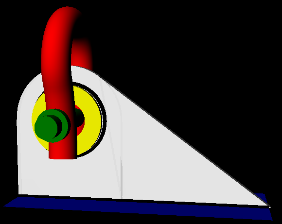
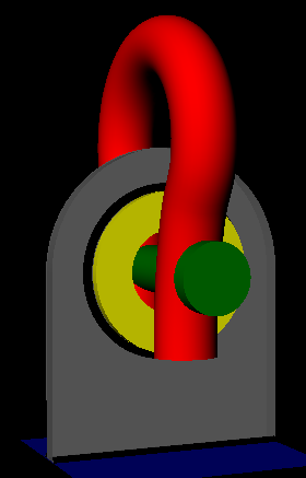
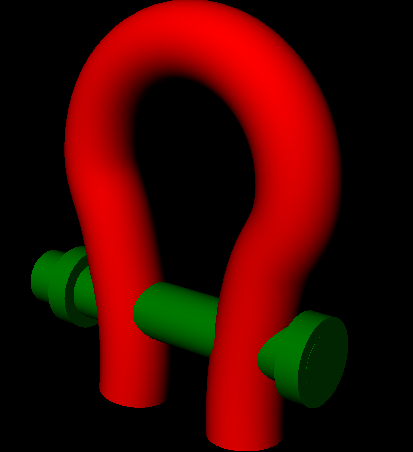
Each lift point consists of a padeye which is welded to the structure and connected to the sling by a shackle. The lifting force acting on the padeye is caused by the weight of the structure and the equipment used. This lifting force is transferred to the sling by a shackle put through the padeye pinhole, creating a pinned connection.
The padeyes that are used in practice have various geometries, depending on the type of load.
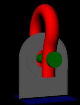
TYPE OF PADEYES
In case of a solely vertical force the geometry is symmetrical. However in the case of a force under an in-plane angle , the geometry is asymmetrical due to the different force components.
- NORMAL LIFTING PADEYE
In case of a solely vertical force the geometry is symmetrical. However in the case of a force under an in-plane angle , the geometry is asymmetrical due to the different force components.
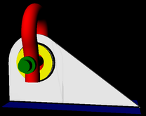
- OFFSHORE HEAVY LIFTING PADEYE
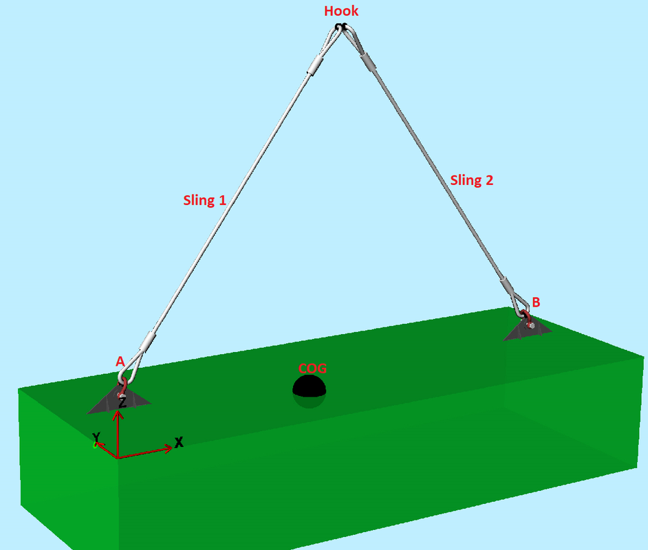
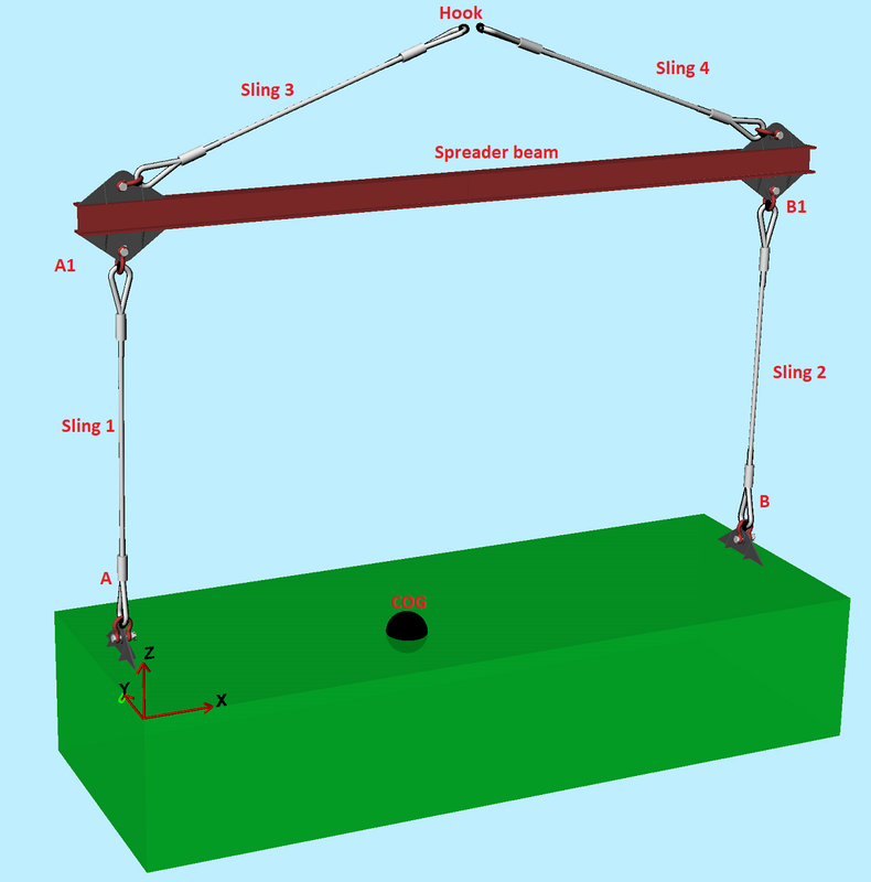
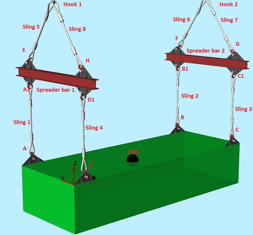
Asymmetric geometry is used in Heavy Lifting, because the force is acting under an angle. In many cases an intermediate spreader bar is used between the crane and the lift point. The spreader bar is used to ensure that the slings are acting under an angle within the allowed range
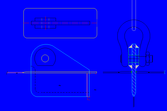
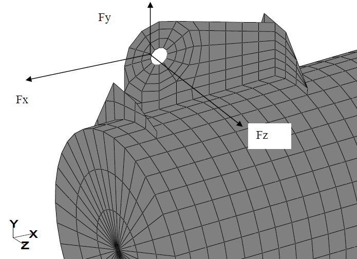
this pinned connection the force has its origin at the centre of the shackle pin cross-section, which is acting in the centre of the pinhole. Shackle connecting the padeye and sling, working under an angle . The pinhole centre lies at a height above the bottom of the main plate. Because the sling is acting under an angle in the plane of the main plate, the force at the pinhole will be under the same angle. Due to this angle of the force , the force can be divided into a vertical component Fy and a horizontal component Fx. Because the horizontal force components is acting at a height , this will result in an in-plane bending moment also.
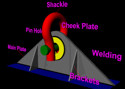
- PADEYES FOR OFFSHORE PLATFORM LIFTING
PADEYE ARRANGEMENT AND ORIENTATION
Bad design: Padeyes Too large hole in padeye
padeyes are welded with fillet welds on the ouside of the frame n Padeye plate is not in the correct angle n 2 shackles are joined together
Padeye attached later on an ISO-container: • padeye-construction gives lack in continuity between toprail and corner post • ISO-containers are not suited for use offshore (for instance the top beam is only a thin L-beam
PADEYE GEOMETRY
the geometry of the padeye must match the size of shackle to be used to ensure a rated connection between the equipment and the lifting set.
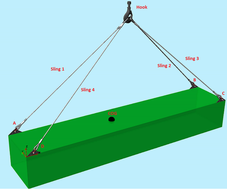
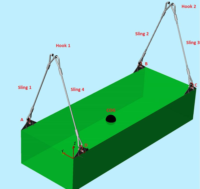
For straight lifting angles a symmetric padeye design should be used, for a multi-point lift as in a offshore container or frame then a nonsymmetric design can be used. If required plated supports can be added to the symmetric design to increase the lateral stiffness of the padeye, useful when the padeye will be subjected to dynamic load angles. For a multi-point lift it is essential that the padeyes point directly to the lift point centre to prevent lateral bending moments on the padeyes,
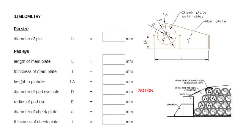
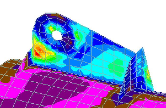
a pad eye consists of a main plate and occasional ring stiffeners. The main plate is conducted with a pair of cheek plates to stiffen the pinned connection and to prevent the main plate from failing due to bearing stress. The ring stiffeners are attached to the main plate to take on the radial and lateral forces and prevent excessive deformation of the CHS.
The outside radius of the padeye main plate shall be no less than the diameter of the pin hole.
For padeyes rated above 2000kg capacity cheek plates must be fitted to reduce the play in the shackle-padeye connection. These must be fitted as additional plates welded onto the padeye profile and not a single boss
The pad eye thickness at the hole shall not be less than 75% the inside width of a shackle suitable for the RSF of the padeye.
The padeye hole diameter should be carefully selected to fit the shackle pin diameter. For strength purposes the difference in hole and pin diameter should be as small as possible, but shackle pin maximum diameter including tolerance should be considered in order to ensure that the pin will enter the hole. For padeyes with significant (i.e. > 10%) out of plane loading, it is recommended that the shackle pin diameter is not less than 94% of the padeye hole diameter.
The diameter of the holes in the padeye shall match the shackle used, clearance between shackle pin and padeye hole shall not exceed 6% of the shackle pin diameter.
The thickness of the padeye at the hole shall not be less than 75% of the inside width of the joining shackle The correct design of padeye should be selected based on the particular load application.
Welding All padeyes must be welded to the primary struture by use of full penetration welds. It is good practure to extend the base of the padeye to pass it completely through the structural member which it is connected to. If welding directly onto horizontal plate then the plate must be specified as EMZ grade to prevent delamination of the plate under tensile load. When sizing the correct padeye for your application consider the following:
Post manufacture load testing must be performed prior to equipment use.
For padeyes subjected to side loading fit additional plates to increase the lateral stiffness of the padeye.
To obtain full penetration welding with this design the base plate is slotted into the top frame. Padeye is being prepared and welded with full penetration. Base plate are to have ”Z”-quality.
Bad design: Padeyes Too large hole in padeye
padeyes are welded with fillet welds on the ouside of the frame n Padeye plate is not in the correct angle n 2 shackles are joined together
Padeye attached later on an ISO-container: • padeye-construction gives lack in continuity between toprail and corner post • ISO-containers are not suited for use offshore (for instance the top beam is only a thin L-beam
PADEYE GEOMETRY
the geometry of the padeye must match the size of shackle to be used to ensure a rated connection between the equipment and the lifting set.
For straight lifting angles a symmetric padeye design should be used, for a multi-point lift as in a offshore container or frame then a nonsymmetric design can be used. If required plated supports can be added to the symmetric design to increase the lateral stiffness of the padeye, useful when the padeye will be subjected to dynamic load angles. For a multi-point lift it is essential that the padeyes point directly to the lift point centre to prevent lateral bending moments on the padeyes,
a pad eye consists of a main plate and occasional ring stiffeners. The main plate is conducted with a pair of cheek plates to stiffen the pinned connection and to prevent the main plate from failing due to bearing stress. The ring stiffeners are attached to the main plate to take on the radial and lateral forces and prevent excessive deformation of the CHS.
- MAIN PLATE
The outside radius of the padeye main plate shall be no less than the diameter of the pin hole.
- CHEEK PLATE
For padeyes rated above 2000kg capacity cheek plates must be fitted to reduce the play in the shackle-padeye connection. These must be fitted as additional plates welded onto the padeye profile and not a single boss
- PIN HOLE DIAMETER
The pad eye thickness at the hole shall not be less than 75% the inside width of a shackle suitable for the RSF of the padeye.
The padeye hole diameter should be carefully selected to fit the shackle pin diameter. For strength purposes the difference in hole and pin diameter should be as small as possible, but shackle pin maximum diameter including tolerance should be considered in order to ensure that the pin will enter the hole. For padeyes with significant (i.e. > 10%) out of plane loading, it is recommended that the shackle pin diameter is not less than 94% of the padeye hole diameter.
The diameter of the holes in the padeye shall match the shackle used, clearance between shackle pin and padeye hole shall not exceed 6% of the shackle pin diameter.
The thickness of the padeye at the hole shall not be less than 75% of the inside width of the joining shackle The correct design of padeye should be selected based on the particular load application.
- SHACKLE SIZING
- WELDING
Welding All padeyes must be welded to the primary struture by use of full penetration welds. It is good practure to extend the base of the padeye to pass it completely through the structural member which it is connected to. If welding directly onto horizontal plate then the plate must be specified as EMZ grade to prevent delamination of the plate under tensile load. When sizing the correct padeye for your application consider the following:
- NDT & LOAD TEST REQUIREMENT
Post manufacture load testing must be performed prior to equipment use.
- TRANSVERSE BRACKETS REQUIREMENT
For padeyes subjected to side loading fit additional plates to increase the lateral stiffness of the padeye.
- INSERT PLATE
To obtain full penetration welding with this design the base plate is slotted into the top frame. Padeye is being prepared and welded with full penetration. Base plate are to have ”Z”-quality.
