 Jacket Transportation
Jackets are fabricated in yards and transported to the field on barge, and then installed by derrick barge by lifting/upending.
Jacket transportation study includes
- Transportation ballast plan,
- Stability analysis
- Barge longitudinal strength check,
- Motion and acceleration response analysis
- Air gap Calculation (for wave slamming assessment on jacket leg members)
- Bollard pull calculation (for Towing Tug Selection).
Transportation route shall follows the IMO approved routing in target region. The route chosen is the most direct, taking in to account any possible obstructions or navigational dangers along the route. Towing speed can be chosen between 3 to 8 knots and towing periods can be calculate accordingly.
Maximum sea states to be considered for the transportation shall be taken from 10 years extreme return period of Towing Route and installation site 1 year extreme return period.Both data sets are subsequently compared to derive the maximum sea states for the study.
The maximum sea-states monthly significant wave height Hs and its corresponding one-minute mean wind speed in the same month shall be used for stability and motion response analysis. To determine the range of probable peak periods, Tp, adjusted for the speed of the barge.
Maximum motions values shall be taken as the maximum of all the sea states.To compute wave drift force,Bollard Pull Requirement shall be checked for Range of Peak Period for Different Hs Support Frame shall be installed before loadout and seafastening and bracket shall be installed after the loadout operation. Unrestricted Navigation SWBM & SWSF shall be used for transportations intended to be in any area and any period of the year.Lightship weight distribution of the barge based on barge stability booklet shall be used for these calculations.
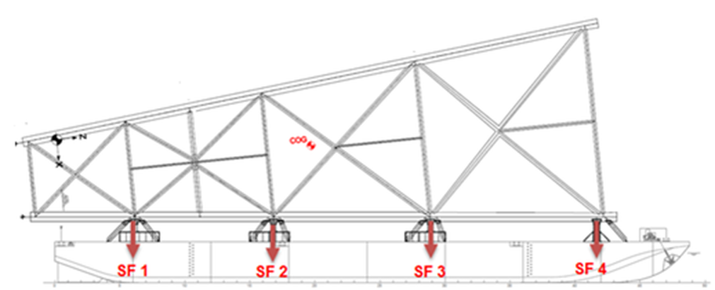
Jacket shall be positioned on the Support Frames from the barge frames. These frames shall be aligned with existing web frames or bulkheads for better load transfer.The jacket is supported by the support frame and seafastening. Stools can be inserted between Support Frame and jacket for better connectivity.
Jacket weight and jacket COG position used for various conditions shall be used for stability and motion response study. Normal COG and COG Shift shall be used for longitudinal strength check.
Jacket weights shall be distributed through support frame location.
Barge is checked according to IMO – MSC 267 (85) Code of Intact Stability, Part B – Recommendation for Certain Types of Ships – Pontoon criteria. Free surface effect shall be considered for (intact and damaged) stability analysis. The criteria are presented hereafter:
- The area under the righting lever curve up to the angle of maximum righting lever should not be less than 0.08 meter-radians (4.58 meter-degree).
- The static angle of heel due to a uniformly distributed wind load of 540 Pa (wind speed 30 m/s) should not exceed and angle corresponding to half the freeboard for the relevant loading condition, where the lever of wind heeling moment is measured from the centroid of the windage area to half the draught.
- The minimum range of stability should be:
- For L ≤ 100 m: 20º;
- For L ≥ 150 m: 15º;
- For intermediate length: by interpolation.
Barge stability is shall also be checked according to NDI Guidelines for Marine Transportations
- Area under righting moment curve to be 40% in excess of wind overturning moment curve at second intercept of righting moment
- The initial metacentric height should be not less than 0.15 m.
- The intact range of stability, about any horizontal axis, defined as the range between 0o degrees inclination and the smallest angle at which the righting arm (GZ) becomes negative shall not be less than 36o degrees. (For large vessel with length > 76m and breadth > 23m)
Barge shall be checked for following Damaged Stability Criteria
- The wind velocity used for overturning moment calculations in the damage condition shall be 26 m/s (50 knots) or the wind used for the intact calculation if less. It shall apply in the most critical direction.
- The unit should have sufficient reserve stability in a damaged condition to withstand the wind heeling moment using the wind speed superimposed from any direction. In this condition the final waterline, after flooding, should be below the lower edge of any downflooding opening
The range of angle calculated from the 2nd intercept and the GZ curve is known as the angle vanishing stability while the angle of the 1st intercept is angle of equilibrium. The range of stability is calculated by subtracting the angle of equilibrium from the angle of vanishing stability.
Class approved Still Water Shear Forces and Bending Moments values shall be used as maximum allowable values for jacket transportation.
These details shall be included in calculations
- The lightship weight distribution along the hull,
- The ballast water weight distribution along the hull,
- The weight distribution of the jacket/cargo along the hull,
- The weight distribution along the hull of all the other equipments, cargo, etc., added on the vessel for the operation (i.e. equipments which are not included in the lightship weight).
- The buoyancy force distribution along the hull when the vessel is in equilibrium (still water condition).
Frequency domain study can be used to predict the motion of the barge loaded with Jacket.The roll damping from bilge keel shall be included in the analysis.Limiting waves Hs with different peak periods shall be used to calculate the barge motions and the accelerations at the COG of the jacket.Wave energy distribution shall be represented with JONSWAP spectrum or other location specific spectrum with appropriate peak parameter.The maximum surge, sway, heave, roll, pitch and yaw results are calculated at the COG of the jacket. These are maximum values and do not necessarily occur at the same time.
Lower VCG and lower boundary weight may bring the natural roll period of the system closer to wave excitation period and generate larger response, so various weights and VCG heights shall be checked.In the motion analysis, we need to determine the maximum motion of the vessel. The LCG, TCG and VCG based on the COG envelop shall be used for the study.
The hull inertia of barge is calculated as follows:
- Roll inertia radius: Rxx = Breadth/3
- Pitch and Yaw inertia radius: Ryy = Rzz = LOA/4
All inertia matrices shal be transferred to the COG of the system by the Huygens formula.Jacket and Support Frame radius of gyration shall be calculated and to be added with barge.
Roll motion is governed by the roll damping, which is caused by mainly
- The wave radiation,
- The viscous effects on the hull
For sea-keeping analysis, the standard procedure is to model these two components of roll damping as the sum of:
- A linear term accounting for the wave radiation damping
- An additional viscous damping is added using the following quadratic formula
Barge shall be towed to the field location; the bollard pull requirement for the towing tug shall be calculated as the sum of Wave drift force, Wind loads and Current loads.
The extreme environment with no forward speed shall be considered. Towing route and the field environmental conditions shall be taken into account for standoff period in the event of bad weather prior to the installation.
The calculation of the wave drift force has been carried on based on the paper “A Lagally formulation of the wave drift force”
The wave drift force is computed For every design wave height with varying wave periods.
For wind loads, the wind screen area shall be used. The wind height and shape coefficients are taken from DNV-OS-C301 “Stability and Watertight Integrity”
The current loads are taken from the equation F = Cx × Scur × V2, with Cx being the current force coefficient on the bow = 2.89 Nsec2/m4 and Scur being the wetted surface area of the hull including appendages, as defined in API RP 2SK.
The current force equation is shown hereafter:
Fcurrent = 2.89 × Scur × Vcur2
Where,
Scur = wetted surface area
The actual extreme condition bollard pull shall be calculated taking into the account both towing route and installation field.Towing Pull Requirement is sum wave drift force, wind force and current force.If the required bollard pull (BP) is higher than 90MT and Hs lower than 2.0m, tug efficiency of 0.8m is used. Otherwise, the value of 0.75 is used.If the required BP is between 30 and 90MT and Hs higher than 2.0m, tug efficiency formula of 52.5+BP/4 is used. The value will be iterated until the value of Tug efficiency converges. For Hs lower than 2.0m, the value of 0.8 is used.If the required BP is below than 30MT and HS is lower than 2.0m, tug efficiency formula of 50+BP is used while for HS is higher than 2.0, the formula of 30+BP is used. The value will be iterated until the value of Tug efficiency converges.
The air gap shall be checked at the overhanging edge of the jacket during transportation.
