GAS MANAGEMENT ON LNG CARRIERS
Heat transfer to the liquid LNG cargo from the insulation spaces and the cargo tanks will cause the liquid to boil and boil off vapour to be formed. Cargo tank boil-off must be removed in order to maintain equilibrium within the cargo tanks at the designed operating pressure. The volume of boil off gas is also increased on passage due to the energy dissipated by the agitation of the cargo caused by the motion of the vessel.
Gas normally taken from the vapour header, is delivered to boilers using the low duty compressor after being heated in the gas heater. Low duty compressor, compress the boil off at certain pressure so that it can be feeded to boilers.
The gas management system covers;
Gas management system controls the low duty compressor to maintain gas flow to the boilers. When the tank’s pressure falls to a set point, the low duty compressor will maintain a pressure above the set point automatically.
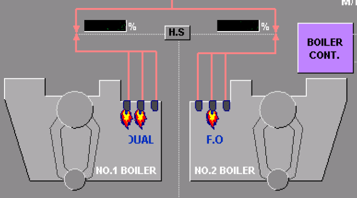
Tank pressure is controlled by the tank pressure control system in order to generate the amount of gas which maintains the tank pressure at the set point by matching the fuel gas requirement from the boilers with the available gas in the tanks. If the boiler fuel mode is fuel gas and the gas requirement from the boiler exceeds the amount of natural boil-off gas from the cargo tanks, the forcing vapouriser is used. In dual fuel mode, the shortage is made up by using additional fuel oil. Any tank overpressure is controlled by the vent control or the steam dump control system, depending on the boiler’s demand.
Settings of the full load voyage condition estimated BOG and the ballast condition estimated BOG is to be implemented using display by operator according to cargo tank condition.
Low Duty Compressor Control
The L/D compressor’s capacity control is dependant on the boiler fuel gas control valve position and the vapour header pressure. The compressor capacity is controlled by the inlet guide vane position.
There are three controllers within the low duty compressor control system:
Outputs from the controllers are selected automatically from the gas management system. The system monitors the vapour header pressure in absolute/gauge mode and controls. The operator must first select the correct voyage mode in which the controllers should operate on the IAS.
Vent Control
In the cargo tank protection mode, the vent control valve will open to full flow (100% capacity) when a pressure on the vapour header exceeds the set maximum threshold value (240 mbar). The valve will stay in this mode until the pressure registered on the vapour header drops below 210mbar at which point the valve will be closed.
In the manual vent inhibit mode, the vent valve will stay closed when the vent inhibit order is set from the wheelhouse. In this mode the manual operation of the vent mast valve is not available. The cargo tank protection mode will override the manual vent inhibit.
.
In the vent control at vent mode, the IAS controls the opening of the vent control valve according to the vapour header pressure while BOG is being fed to the engine room for burning in the boilers. In this mode the manual operation of the vent mast valve is not available.
In the manual vent mode, the operator will manually set the opening (position %) of the vent control valve from the operator’s screen.
Gas Heater Control
The outlet temperature or the BOG through the gas heaters is monitored with the temperature at the outlet from the heater being regulated by the heater inlet valve and heater bypass valve. Under the gas heater trip conditions, the IAS will automatically close the heater inlet valve and open the bypass valve. Both valves will be locked in this condition until the trip condition is recovered. The BMS will receive a signal from the IAS of the heater trip and changes the fuel mode to F.O mode, F.O boost up, immediately.
Forcing vaporizers control
During ballast or laden voyage mode, cargo tank pressure can be maintained by forcing vaporizers control when the boiler is operated in fuel gas mode. Two PID controllers are provided for temperature and flow control. Set point to these controllers will be input manually. The IAS controls stripping/spray pump load from motor current, the stripping/spray header pressure is controlled by controlling the strip return valve.
Gas normally taken from the vapour header, is delivered to boilers using the low duty compressor after being heated in the gas heater. Low duty compressor, compress the boil off at certain pressure so that it can be feeded to boilers.
The gas management system covers;
- Low duty compressor control
- Tank pressure control
- Vent control
- Dump control
- Forcing vaporizers control
Gas management system controls the low duty compressor to maintain gas flow to the boilers. When the tank’s pressure falls to a set point, the low duty compressor will maintain a pressure above the set point automatically.
Tank pressure is controlled by the tank pressure control system in order to generate the amount of gas which maintains the tank pressure at the set point by matching the fuel gas requirement from the boilers with the available gas in the tanks. If the boiler fuel mode is fuel gas and the gas requirement from the boiler exceeds the amount of natural boil-off gas from the cargo tanks, the forcing vapouriser is used. In dual fuel mode, the shortage is made up by using additional fuel oil. Any tank overpressure is controlled by the vent control or the steam dump control system, depending on the boiler’s demand.
Settings of the full load voyage condition estimated BOG and the ballast condition estimated BOG is to be implemented using display by operator according to cargo tank condition.
Low Duty Compressor Control
The L/D compressor’s capacity control is dependant on the boiler fuel gas control valve position and the vapour header pressure. The compressor capacity is controlled by the inlet guide vane position.
There are three controllers within the low duty compressor control system:
- Set point is the highest value of the two (2) boiler fuel gas valves positions
- Set point is the output of the active cargo tank pressure controller
- 2&3 are available for ballast and laden mode respectively during the dual fuel mode.
Outputs from the controllers are selected automatically from the gas management system. The system monitors the vapour header pressure in absolute/gauge mode and controls. The operator must first select the correct voyage mode in which the controllers should operate on the IAS.
Vent Control
In the cargo tank protection mode, the vent control valve will open to full flow (100% capacity) when a pressure on the vapour header exceeds the set maximum threshold value (240 mbar). The valve will stay in this mode until the pressure registered on the vapour header drops below 210mbar at which point the valve will be closed.
In the manual vent inhibit mode, the vent valve will stay closed when the vent inhibit order is set from the wheelhouse. In this mode the manual operation of the vent mast valve is not available. The cargo tank protection mode will override the manual vent inhibit.
.
In the vent control at vent mode, the IAS controls the opening of the vent control valve according to the vapour header pressure while BOG is being fed to the engine room for burning in the boilers. In this mode the manual operation of the vent mast valve is not available.
In the manual vent mode, the operator will manually set the opening (position %) of the vent control valve from the operator’s screen.
Gas Heater Control
The outlet temperature or the BOG through the gas heaters is monitored with the temperature at the outlet from the heater being regulated by the heater inlet valve and heater bypass valve. Under the gas heater trip conditions, the IAS will automatically close the heater inlet valve and open the bypass valve. Both valves will be locked in this condition until the trip condition is recovered. The BMS will receive a signal from the IAS of the heater trip and changes the fuel mode to F.O mode, F.O boost up, immediately.
Forcing vaporizers control
During ballast or laden voyage mode, cargo tank pressure can be maintained by forcing vaporizers control when the boiler is operated in fuel gas mode. Two PID controllers are provided for temperature and flow control. Set point to these controllers will be input manually. The IAS controls stripping/spray pump load from motor current, the stripping/spray header pressure is controlled by controlling the strip return valve.
