Click to set custom HTML
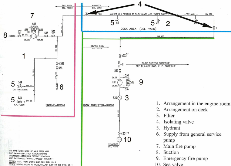
Fire fighting arrangement has to carry sea water from sea bottom to fire hydrants.System involves fire fighting pumps,main line,valves,couplings,hoses and monitors.A minimum of two main fire fighting pumps and one emergency pumps are used for this system. Main fire pumps shall be located in different compartments separated by at least A0 bulkhead and shall be powered by main engines however emergency fire pump shall be located outside of engine room and driven by independent engine or emergency power system.Main fire line between engine room and deck shall consist of a valve so that in case of fire in engine room,main line shall be pressurized by emergency fire pump.hydraulically-driven pumps are to have independent power units and controls without interconnections.
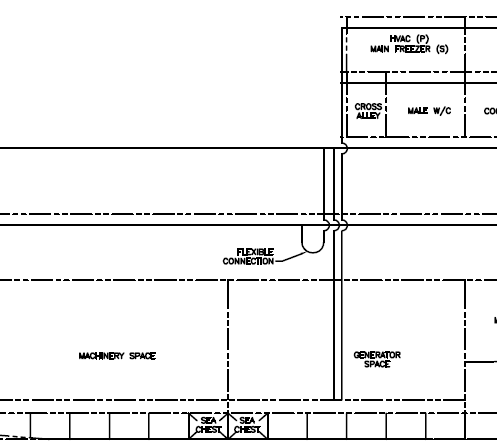
The sea chest, suction piping and discharge piping arrangements to the fire main, as well as the pump and valve controls, must be arranged so as to be totally independent from the other pump and are not to be located in or enter into the space containing the other pump.The sea chest and suction pipe for one of the main fire pumps (or the emergency fire pump), which is located outside of the machinery space, may be located in the machinery space.It should be noted that if the suction or discharge piping is permitted to be within a category “A” machinery space, the piping is to be all welded except for flange connections to the sea inlet valve.
General Principles of the Fire Main System
The fire main is a system consisting of sea inlet(s), suction piping, fire pumps and a distributed piping system supplying fire hydrants, hoses and nozzles located throughout the vessel. Its purpose is to provide a readily available source of water to any point throughout the vessel which can be used to combat a fire and is considered the backbone of the fire-fighting systems onboard a vessel. Through the fire main system, the firefighter is provided with a reliable and versatile system capable of providing a number of different methods with which to engage a fire. Water can be supplied as a straight stream for combating deep seated fires, as a spray for combating combustible liquid fires where cooling and minimum agitation is desired or as a means to protect personnel where cooling is the primary effect desired.
Main fire pumps shall have enough power to pump water to each part of the ship. Friction losses in fire lines shall be calculated and used for pump capacity determination.
- Fire fighting pipes exposed to decks shall be insulated by frostproof materials.
- Drain cocks are provided at lower location of pipes and venting are provided at top location.
- Fire main pipes are shop tested at 1.5 times of design pressure.
- Hydrants shall be located 700 to 800 mm higher from the deck.
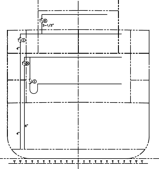
- Expansion joints to be provided in main fire line at regular interval and type joints are arranged in other straight pipe lines at regular interval.
- Penetrating piece shall be used in watertight bulkheads where these pipes are penetrating these bulkheads.


