This article describes the intact and damage stability characteristics of a drill ship and the compliance with the requirements as set out by IMO and IMO MODU Code. This will present a set of maximum VCG values for various drafts. The Max VCG values are calculated for the vessel with the canisters in a low position
The Max VCG values shall be based on the wind heeling moments as calculated by block method or wind tunnel tests. A 10% contingency shall be added to the wind heeling moments to create some margin for possible future changes of the wind contour of the vessel.
REQUIRED INFORMATION
Following information are required for stability assessment
PERMEABILITY
DOWN FLOODING POINTS
Weather tight downflooding points such as hatch,door,vent pipes etc shall be considered for damage stability analysis. Unprotected downflooding points which can not be closed during flooding shall be considered for intact stability analysis. Funnel,ventilators etc are unprotected downflooding points.
STABILITY REQUIREMENTS
The loading conditions are divided in three types of loading conditions,
Different intact stability requirements according to IMO MODU Code and DNV OS are applicable in all modes of operation.
The following intact stability criteria are applied for sailing and standby conditions:
The following intact stability criteria are applied for drilling (operational) conditions:
Damage stability is calculated in accordance with MODU-code with a wind speed of 50 knots applied for the damage calculations.
IMO A.749 STATIC INTACT STABILITY
The Max VCG values shall be based on the wind heeling moments as calculated by block method or wind tunnel tests. A 10% contingency shall be added to the wind heeling moments to create some margin for possible future changes of the wind contour of the vessel.
REQUIRED INFORMATION
Following information are required for stability assessment
- General Arrangement
- Watertight Subdivision Plan
- Lines plan
- Loading Conditions
- Hydrostatic Particulars
- Wind tunnel investigation on the wind and current load on drillship
PERMEABILITY
- Storerooms 0.95
- Machinery spaces 0.85
- Accommodation spaces 0.95
- Tanks and voids 0.95
DOWN FLOODING POINTS
Weather tight downflooding points such as hatch,door,vent pipes etc shall be considered for damage stability analysis. Unprotected downflooding points which can not be closed during flooding shall be considered for intact stability analysis. Funnel,ventilators etc are unprotected downflooding points.
STABILITY REQUIREMENTS
The loading conditions are divided in three types of loading conditions,
- Sailing conditions
- Drilling conditions
- Standby conditions
Different intact stability requirements according to IMO MODU Code and DNV OS are applicable in all modes of operation.
The following intact stability criteria are applied for sailing and standby conditions:
- IMO resolution A.749
- IMO resolution A.562; Severe weather criterion (wind pressure 0.504 t/m^2)
- IMO MODU code (wind speed 100 knots)
The following intact stability criteria are applied for drilling (operational) conditions:
- IMO resolution A.749
- IMO resolution A.562; Severe weather criterion (wind pressure 0.504 t/m^2)
- IMO MODU code (wind speed 70 knots)
Damage stability is calculated in accordance with MODU-code with a wind speed of 50 knots applied for the damage calculations.
IMO A.749 STATIC INTACT STABILITY
- Area under the righting arm curve from 0 to 30 degrees > 0.055 mrad
- Area under the righting arm curve from 30 to 40 degrees or down flooding point, whichever comes first > 0.090 mrad
- Righting arm at 30 degrees > 0.200 m
- Maximum righting arm should occur at an angle of not less than 25 degrees
- Minimum initial metacentric height > 0.150 m
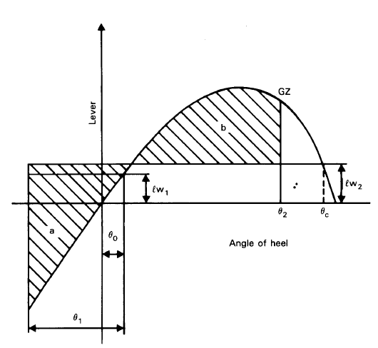
IMO A.562 SEVERE WEATHER CRITERION
Area b’ equal or greater than ‘area a’ The figure below shows this criterion.
The wind heeling levers lw1 and lw2 are constant values at all angles of inclination and should be calculated as follows:
lw1 and = P * A * Z [m]
∆
lw2 = 1.5 * lw1 [m]
where:
P = 0.0514 [t/m2]
A = projected lateral area of the portion of the ship and deck cargo above the waterline [m2]
Z = vertical distance from the centre of A to the centre of the underwater lateral area or approximately to a point at one half the draught [m]
∆ = displacement [t]
The angles in the above figure are defined as follows:
θ0 = Angle of heel under action of steady wind
θ1 = Angle of roll to windward due to wave action
θ2 = Angle of downflooding (θf) or 50° or θc whichever is less, where:
θf = Angle of heel at which openings in the hull, superstructures or deckhouses which cannot be closed weathertight immerse
θc = Angle of second intercept between wind heeling lever lw2 and GZ curves
The angle of roll (θ1) should be calculated as follows:
θ1 = 109k * X 1 * X 2 *r * s [deg]
where:
r = 0.73 ± 0.6OD/d with
OG = the distance between the centre of gravity and the waterline [m] (+ if the centre of gravity is above the waterline, - if it is below)
d = is the mean moulded draught of the ship [m]
with
T = 2 * C * B [s]
sqrt(GM )
where C = 0.373 + 0.023 (B/d) – 0.043 (L/100)
L = waterline length of the ship [m]
B = moulded breadth of the ship [m]
D = mean moulded draught of the ship [m] CB = block coefficient
Ak= total overall area of bilge keels, or area of the lateral projection of the bar keel or sum of these areas [m2]
GM = metacentric height corrected for free surface effect [m]
IMO MODU-CODE INTACT STABILITY CRITERIA
In addition to the criteria above, MODU Code has additional requirements to the intact stability. The stability of a unit in each mode of operation should meet the following criteria as laid down in section 3.2 and 3.3 of IMO MODU Code:
- In general a wind velocity of 36 m/s (70 knots) for offshore service should be used for normal operating conditions and a minimum wind velocity of 51.5 m/s (100 knots) should be used for severe storm conditions
- Where a unit is to be limited in operation to sheltered locations (protected inland water such as lakes, bays, swamps, rivers etc.) consideration should be given to a reduced wind velocity of not less than 25.8 m/s (50 knots) for normal operating conditions.
- The area under the righting moment curve to the second intercept or downflooding angle, whichever is less, should not be less than 40% in excess of the area under the wind heeling moment curve to the same limiting angle.
- The righting moment curve should be positive over the entire range of angles from upright to the second intercept.
IMO MODU-CODE DAMAGE STABILITY CRITERIA
Assumed extent of damage:
- Horizontal penetration: 1.5 m
- Vertical extent: from the base line upwards without limit
- If damage of lesser extent results in a more severe condition, such damage shall be assumed in the calculations.
- The distance between effective watertight bulkheads or the nearest stepped portions which are positioned within the assumed extend of horizontal penetration should be not less than 3.0 m; where there is a lesser distance, one ore more of the adjacent bulkheads should be disregarded.
- All piping, ventilation systems, trunks etc. within the extend of damage should be assumed to be damaged. Positive means of closure should be provided at watertight boundaries to preclude the progressive flooding of other spaces which are intended to be intact.
the unit should comply with the following criteria:
- The unit should have enough freeboard and be subdivided by means of watertight decks and bulkheads to provide sufficient buoyancy and stability to withstand in general the flooding of any compartment in any operating or transit condition consistent with the damage assumptions.
- The unit should have enough reserve stability in a damaged condition to withstand the wind heeling moment based on a wind velocity of 25.8 m/s (50 knots) superimposed from any direction. In this condition the final waterline, after flooding, should be below the lower edge of any downflooding opening.
WIND HEELING MOMENTS
The wind heeling moments at several drafts shall be obtained by wind tunnel tests or other appropriate calculation methods; this is in accordance with IMO MODU Code . Wind tunnel Tests shall be performed for operational range of drafts at regular interval.Wind heeling moments at intermediate draft shall be inter/extrapolated.
The wind heeling moments shall be calculated in accordance with;
- IMO RES. A562 Severe Wind and Rolling for intact stability
- MODU CODE 100 knot wind speed for intact stability
- MODU CODE 70 knot wind speed for itact stability
- MODU CODE 50 knot wind speed for damage stability
IMO A562 Severe Wind and Rolling
The IMO A562 criterion uses an overall wind pressure of 504 N/m^2
Formula Wind heeling moment = P*A*Z*G*1/9810 [ton*m]
Where
P = Wind pressure [N/m^2]
A = projected lateral area of the structural member exposed to the wind [m^2] Y = centre of lateral resistance [m]
Z = vertical distance from centre of A to Y [m]
G = Gust factor = 1.5 [-]
For operating conditions the MODU-code considers a wind speed of 36 m/s (70 knots) and for severe storm conditions the MODU-code considers a wind speed of 51.5 m/s (100 knots).
The wind tunnel tests provides dimensionless coefficients for wind force and wind heeling moments.
Dividing the calculated wind heeling moment by the wind force, results in a lever. This lever is adapted, since the wind heeling moment in the wind tunnel is calculated with regard to the waterline of the vessel. In reality the thrusters will compensate the wind force as long as this force is lower than the maximum bollard thrust of the thrusters. The total wind lever is therefore a summation of the calculated lever from the wind tunnel tests and the lever of the thrusters to the waterline.
At high wind speeds the bollard thrust of the thrusters are lower than the wind force. The surplus of wind force is compensated by the lateral resistance of the vessel. This lateral force has a lever with regard to the waterline of 50% of the draft. At high wind speeds the total wind heeling moment is composed of the thrust heeling moment and a lateral heeling moment which has a reduced lever.
A 10% contingency margin shall be added to these wind heeling moments for possible future changes in equipment or contour of the vessel. This results in the wind heeling moments which were used for the Max-VCG calculations.
The applicable wind heeling moments for the loading conditions are obtained by interpolation of these calculated wind heeling moments.
MAX ALLOWABLE VCG CURVE
The maximum allowable VCG curve is a combination of the limitations resulting from the intact condition maximum VCG curve and the damage condition maximum VCG curve.
A maximum allowable intact VCG curve shall be prepared by complying with the IMO A749, A562 and IMO MODU. The intact stability curves shall be determined for even keel and -0.5 degrees and 0.5 degrees trim angels. The curves shall be determined for operationl draft range with a draft step of 1.0 m.
According to IMO MODU Code damage stability requirements, damage occurs between transverse watertight bulkheads with a 1.5m horizontal penetration. The minimal longitudinal extension of the damage is 3m. When the watertight bulkheads are spaced more than 3m apart, only one watertight zone is damaged in each case.
A maximum allowable damage VCG curve has been prepared complying with the IMO MODU Code 50 knots wind velocity and DNV OS damage stability requirements.
The damage stability curve is determined for even keel and +/- 0.5 degrees trim angles. The curves are determined for a draft range of 7.0 to 12.0 m with a draft step of 1.0 m. The maximum allowable summer loadline draft is 12.0 m.
Results of damage stability
The final waterline after flooding shall be below the lower edge of any downflooding opening. The height of the downflooding opening which is the nearest to the waterline is taken as the margin in analysis, which is minimized to optimize the Max VCG curves.
INPUT KG VALUES FOR MAX KG IN DAMAGE CASES
The initial input VCG for damage stability calculations are the limiting VCG as derived from the intact stability. The MODU 100 results in the lowest allowable VCG. Not all loading conditions have to apply to the MODU 100 code (only survival loadings) , but all loading conditions do to have apply to the MODU 70 (Operational conditions) code. Therefore the Max VCG-values found from the MODU 70 code are used as input for the Max-VCG calculations for the damaged condition. With some damaged zones and at some drafts, the vessel does not compy with the MODU 50 code. In these cases the VCG was lowered.
