FPSO SPREAD MOORING DESIGN FOR BENIGN WEATHER
SPREAD MOORING DESIGN OF FPSO
An FPSO is located within the production field and process the crude oil received from the production well, and stabilized oil is offloaded to a shuttle tanker using a floating loading hose.
Main objective of the mooring analysis shall be
- Prove that the mooring system is adequate for both monsoon and cyclonic conditions and satisfies the API-RP-2SK code requirements.
- Establish the offsets (maximum) for the worst cases analyzed.
Following loading conditions shall be modelled to get full range of results
- FULLY LOADED
- BALLASTED
Following particulars shall be extracted from stability and loading condition report
- Draft Loaded, TL Loaded displacement
- LCG position forward of amidships VCG position above keel
- Draft Ballast, TB
- Ballast displacement
- LCG position forward of amidships
- VCG position above keel
CRITERIA AND CODE
Classification society requirements and API-RP-2SK codes shall be used to get the criteria on minimum factor of safety (FOS) in intact and single line failure (SLF) cases
- FOS (Intact) should be greater than 1.67.
- FOS (SLF) should be greater than 1.25.
Other criteria set are:
- Sufficient ground length to avoid lift off at anchor and
- Maximum offset to be within those set by riser design as per table below
STORM CONDITIONS
The design of a mooring shall be for extreme conditions. The approach of a tropical storm / cyclone could be from any direction. Therefore only the most onerous of weather parameters shall be used to design the system, assuming that this wave + wind + current combination can approach the installation from any direction.
Order of mooring analysis severity shall be from weather from BEAM-ON, QUARTERING FROM STERN and to HEAD-ON.
Additional intermediate angular positions shall also be checked for sensitivity to mooring system.
Cyclonic storm and monsoon storm conditions shall be considered if there is possibility of occurence
OMNI DIRECTIONAL CYCLONIC STORM
- Significant wave height, wave crossing period and spectrum chosen shall be well defined. Spectrum shall be location based and values of g shall be chosen accordingly, More severe weather conditions use JONSWAP spectrum with g varies from 1.1 to 2.0
- 1-Hour Mean Wind Speed used with an API wind spectrum VERSUS 1-Minute Mean Wind Speed
- Surface current speed
- Wave, wind and current shall be assumed coming from same direction
Beam-on approaching
Quartering from stern
Head-on approaching
Additional four cases of the Beam-on @ 15-degree intervals
OMNI DIRECTIONAL MONSOON STORM
- Significant wave height, wave crossing period and spectrum chosen shall be well defined for monsoon storm separately. Spectrum shall be location based and values of g shall be chosen for monsoon storm, More severe weather conditions uses JONSWAP spectrum where g varies
- 1-Hour Mean Wind Speed used with an API wind spectrum VERSUS 1-Minute Mean Wind Speed
- Surface current speed
- Wave, wind and current shall be assumed coming from same direction
Beam-on approaching
After comparing different storm conditions, severe storm condition shall be checked in more detail
WAVE,WIND AND CURRENT DATA
The environmental data for design shall be based on regional met-ocean analysis
The extreme design case is to be based upon a 100 year return period storm event. FPSO mooring systems are designed for 100 year return period.
Design limits can be surpassed in following cases
- Marine transportation design cases shall be for route and season specific 10 year return period conditions, consistent with typical Marine Warranty Surveyor requirements.
- Installation and abandonment design cases will be evaluated on a case by case basis during FEED with respect to risk and the project plan.
- During extreme conditions tanker loading and drilling operations are expected to be restricted
METHODOLOGY OF ANALYSIS
This flow chart clearly shows the steps involved in the analysis of the mooring system.
The analysis is performed for (a) LOADED and (b) BALLAST drafts of the FPSO and for each draft BEAM conditions are used as the load cases since these are the most critical cases.
Before going for time domain mooring analysis following additional computations shall be performed
- Equilibrium run to obtain the no-environment position and tensions
- Line profile checks and line pre-tensions
- Static run to build stiffness matrix before the model is ready for time domain runs.
Many simulations are performed and for each of the simulation, the maximum tension of the most loaded line is noted.
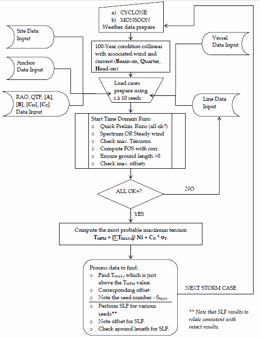
FPSO SPREAD MOORING ANALYSIS FLOW CHART
FPSO HEADING, MOORING LINE ARRANGEMENT AND ASSUMPTIONS
FPSO heading shall be chosen to ward off worst possible environmental loads and minimize mooring arrangement onboard. If worst cyclone is expected to be coming from north-east, its better to arrange fpso in head on arrangement with that direction. However multiple factors are considered for this heading. Swell effect, monsoon direction, nearby platforms etc are considered for heading. If monsoon, cyclones and swell directions are different, then optimized directions shall be chosen so that overall performance is improved.
Mooring lines shall be symmetrical and cost optimization shall be involved while choosing number of lines, anchor, and winches etc. Less number of lines might be cost effective but redundancy in single failure cases will also be low. More lines give more flexibility and redundancy will also be high in case of single line failure.
For simplification following assumptions can be followed however more realistic conditions shall be defined wherever required.
NUMERICAL MODELLING
The vessel particulars, FPSO mesh for representation and fairleads shall be accurately in the model.and following shall be defined before running simulation
Due to corrosion, a reduced diameter of 0.4mm / year shall be considered for fpso design life. Corresponding MBL for reduced chain diameter shall be selected.
The definition of wave and wind spectrum with respective seeds shall be selected
FPSO heading shall be chosen to ward off worst possible environmental loads and minimize mooring arrangement onboard. If worst cyclone is expected to be coming from north-east, its better to arrange fpso in head on arrangement with that direction. However multiple factors are considered for this heading. Swell effect, monsoon direction, nearby platforms etc are considered for heading. If monsoon, cyclones and swell directions are different, then optimized directions shall be chosen so that overall performance is improved.
Mooring lines shall be symmetrical and cost optimization shall be involved while choosing number of lines, anchor, and winches etc. Less number of lines might be cost effective but redundancy in single failure cases will also be low. More lines give more flexibility and redundancy will also be high in case of single line failure.
For simplification following assumptions can be followed however more realistic conditions shall be defined wherever required.
- Seabed is assumed flat
- Riser drag can be included or excluded depending on condition
- One directional approach of the worst 100-year storm shall be assumed for mooring
- 1-minute mean wind speed or API based wind spectrum shall be chosen whichever gives worst loading
- Wave, wind and current approach shall be assumed collinear for conservative approach
- For shallow water depth full QTF matrix shall be chosen as this will give more realistic loads however for deep water it can be simplified.
- Top side projected areas shall be considered more realistic
- OCIMF wind and current coefficients or wind tunnel produced data shall be chosen
NUMERICAL MODELLING
The vessel particulars, FPSO mesh for representation and fairleads shall be accurately in the model.and following shall be defined before running simulation
- Vessel draft, displacement, COG position and radii of gyration.
- The references for computing vessel motion response.
- Added mass [A] matrix
- Damping matrix [B] – Calculation as per guidelines.
- RAO data
- Diagonal and Full QTF data
- OCIMF based wind and current coefficients.
Due to corrosion, a reduced diameter of 0.4mm / year shall be considered for fpso design life. Corresponding MBL for reduced chain diameter shall be selected.
The definition of wave and wind spectrum with respective seeds shall be selected
FPSO HEADING FOR PERMANENT MOORING
|
ANCHOR SETTINGS RADIUS AND AZIMUTH
|
Load case setting (with JONSWAP wave spectrum profile)
|
Mooring line ground length and profile
|
EQUILIBRIUM CONDITION SET UP
The equilibrium calculation decides the “zero-environment” position of the vessel, the pretensions and builds the stiffness matrix for loading conditions.
TIME DOMAIN CALCULATION
The time domain calculation starts after filling the necessary input. Several seeds are run for each load case and the results are presented in the following section.
RESULTS
This section deals with the Single Line Failure analyses results, run for various seeds for Beam-on cases only. The result which is consistent with the intact results in terms of tension and offsets are selected and rest are rejected.
Maximum offset,Loaded line no.,Fairlead angle,FOS and Ground length for each mooring line shall be calculated.
Factor of safety shall be above the minimum required by API codes and the ground length sufficient enough to avoid any uplift at the anchor.
Additional environmental loading conditions shall be analyzed
HIGHER PRE TENSION SETTING
if maximum offset is not acceptable to the riser designers. Further analysis shall be required higher pretension on the mooring lines.Higher pretensions usually results in higher mooring loads. If designed mooring system has excess capacity to absorb higher line load, larger pull-in winch capacity and hook-up gear shall be required for installation of mooring system on FPSO.
With Higher Pre-tension, following shall be checked
With an installation (ballast condition) higher pretension range for all mooring lines shall achieve and fulfill following requirements.
The equilibrium calculation decides the “zero-environment” position of the vessel, the pretensions and builds the stiffness matrix for loading conditions.
TIME DOMAIN CALCULATION
The time domain calculation starts after filling the necessary input. Several seeds are run for each load case and the results are presented in the following section.
RESULTS
This section deals with the Single Line Failure analyses results, run for various seeds for Beam-on cases only. The result which is consistent with the intact results in terms of tension and offsets are selected and rest are rejected.
Maximum offset,Loaded line no.,Fairlead angle,FOS and Ground length for each mooring line shall be calculated.
Factor of safety shall be above the minimum required by API codes and the ground length sufficient enough to avoid any uplift at the anchor.
Additional environmental loading conditions shall be analyzed
HIGHER PRE TENSION SETTING
if maximum offset is not acceptable to the riser designers. Further analysis shall be required higher pretension on the mooring lines.Higher pretensions usually results in higher mooring loads. If designed mooring system has excess capacity to absorb higher line load, larger pull-in winch capacity and hook-up gear shall be required for installation of mooring system on FPSO.
With Higher Pre-tension, following shall be checked
- Offsets of the vessel
- Maximum tension values in the chains.
With an installation (ballast condition) higher pretension range for all mooring lines shall achieve and fulfill following requirements.
- All the FOS (Intact) values calculated shall be greater than 1.67, the minimum required by API-RP-2SK.
- All the FOS (SLF) values calculated shall be greater than 1.25, the minimum required by API-RP-2SK.
- A minimum length of ground length shall be available.
