offshore mooring design
OFFSHORE MOORING DESIGN BASICS
This article describes the guidelines which will be used for the design of mooring system
A number of recognised standards and design codes covering moorings are already in existence.The default standard for mooring system design and approval is ISO 19901-7.
OFFSHORE MOORINGS
The International Standard ISO 19901-7, represents the most modern and widely accepted set of criteria and guidelines for offshore moorings.DNV OS E301, Position Mooring (POSMOOR E301), is an acceptable alternative to ISO 19901-7 when used in conjunction with DNV RP C205. Although the environmental loads experienced by a vessel moored in a sheltered inshore location or alongside a quayside are likely to be significantly lower than those it may experience offshore, the risk profile of these types of mooring is high due to a combination of the following factors:
OCIMF, is considered appropriate for evaluating quayside mooring requirements of marine vessels such as tankers. It also provides good guidance on the use of quayside moorings and on design factors of safety for common vessel connections such as bitts, Smit brackets and Panama chocks.
Details of the operation to be undertaken should be established, including:
- Offshore catenary or taut leg moorings of mobile offshore units (MOU)
- Offshore catenary or taut leg mooring of floating offshore installations (FOI)
- Inshore mooring of MOUs and FOIs, e.g. for stacking
- Temporary mooring of offshore installations in an afloat condition during construction, installation or decommissioning
- Quayside mooring of MOUs and FOIs, e.g. during maintenance or conversion
- Mooring of vessels during load-outs and installation operations.
A number of recognised standards and design codes covering moorings are already in existence.The default standard for mooring system design and approval is ISO 19901-7.
OFFSHORE MOORINGS
The International Standard ISO 19901-7, represents the most modern and widely accepted set of criteria and guidelines for offshore moorings.DNV OS E301, Position Mooring (POSMOOR E301), is an acceptable alternative to ISO 19901-7 when used in conjunction with DNV RP C205. Although the environmental loads experienced by a vessel moored in a sheltered inshore location or alongside a quayside are likely to be significantly lower than those it may experience offshore, the risk profile of these types of mooring is high due to a combination of the following factors:
- Offshore mooring systems are generally designed for large deployed lengths of mooring wire or chain whereas inshore moorings will generally have short taut lines which can lead to very high tensions and can result in uplift on anchors
- High consequence of failure given the proximity to shore, other assets and limited response time
- Potential lack of suitable or degraded connection points on the vessel and onshore, e.g. quayside
- Uncertainty in the calculation of environmental forces due to wind shear effects and shallow water blockage effects
- Potential limitations on the ability to adjust moorings and balance the line tensions in adverse weather conditions
- Potential difficulty in knowing the actual tensions in the lines, in other words, a lack of instrumentation
- Potential for failures due to chafe points and abrasion (especially for quayside moorings).
OCIMF, is considered appropriate for evaluating quayside mooring requirements of marine vessels such as tankers. It also provides good guidance on the use of quayside moorings and on design factors of safety for common vessel connections such as bitts, Smit brackets and Panama chocks.
Details of the operation to be undertaken should be established, including:
- Nature of operation
- Timing, e.g. dates
- Duration
- Any operational mooring system performance criteria
- Whether the mooring system will be active or passive; an active system allows line tension/length adjustment
- Manned or unmanned and, if manned, whether on a 24 hour basis.
MOORING LOCATION
- Geographical location, e.g. grid coordinates and possible local currents, e.g. river outflows
- Water depth including bathymetry covering the full area of the mooring spread
- Seabed conditions, e.g. soil type
- Geotechnical information, e.g. soil properties derived from core samples, if required
- Details of any existing installations or infrastructure on the surface and subsea, documented by reliable surveys
- For inshore or quayside moorings some details of the local topography may be required to help determine the wind sheltering effects and the wind shear profiles that should be applied
- Quay wall section drawings detailing water levels and elevation of fendering arrangements
- Capacity of quayside bollards
MOORING DESIGN ENVIRONMENTAL CONDITIONS
- Design seastate, usually characterised by significant wave height and peak period, together with a parametric wave spectrum, e.g. JONSWAP spectrum and peak enhancement factor
- Design wind speed and, if applicable, gust spectrum
- Design current and, if applicable, current profile
- Long period swell and direction,
- Minimum temperature if below 0ºC.
REQUIRED VESSEL DETAILS FOR MOORING ANALYSIS
- Intended draught(s)
- Details of loading condition - displacement, VCG, LCG, mass moments of inertia or radii of gyration in roll, pitch and yaw.
- Environmental loading and response characteristics (for all relevant draughts and water depths):
- Wind load coefficients
- Current load coefficients
- Quadratic Transfer Functions (QTFs) and low frequency added mass and damping
- One of the following wave-frequency response characteristics:
- Response Amplitude Operators (RAOs) or
- Wave Load RAO's and frequency dependent added mass and damping.
- Fairleads - type, positions and documented structural capacity, including supporting structure
- Winches or windlasses - number, type, brake capacity, stopper capacity, stall capacity, pawl details, etc.
- Position and capacity of onboard bollards, mooring bitts or Smit brackets
- Dimensions, condition and load capacity of anchor racks (cow catchers).
- Thrusters - number, type, thrust and positions and operational; status
- Control system - manual joystick or fully dynamically positioned (TA / ATA)
- Critical failure modes - thrust available following a worst case single point failure.
MOORING SYSTEM DETAILS
- Anchors - number, type and weight
- Mooring line make-up, length, type and age of each component
- Mooring line nominal diameter, minimum breaking load, axial stiffness (EA, where E = Young’s modulus and A = cross section area) and dry and wet weight per unit length
- Latest mooring line inspection report
- Details of any buoys or clump weights
- Details of any connecting hardware
- Condition and operational status of equipment
- Anchor position and mooring pre-tension.
Moorings shall be designed to withstand the loads caused by the most adverse environmental conditions expected for the location and duration of the mooring. An unrestricted operation is one which is effectively free of any environmental limits. An unrestricted mooring is designed to be able to withstand a design environment with a large return period such that the probability of it being encountered is suitably small.
A longer return period will be required when the moored item is high-value, e.g. a concrete production platform under construction. For mooring durations greater than 6 months, 100 year return period can be used. Mobile moorings should generally be designed with reference to a 10 year return period when in the vicinity of any other infrastructure. Where a mobile mooring is in an open location, with reduced consequence from mooring failure, a five year return period may be acceptable. When evaluating the consequence of failure, consideration should be given to whether risers will be connected, proximity to other installations and the type of operation being undertaken. For pipe laying operations, the expected duration of the operation, plus a suitable contingency value, should be addressed.
Directional metocean data may also be used with suitable spreading functions to reflect directional divergence in the design environment. Wind speeds should be referenced at 10m above the still water level.
For permanent moorings Steady one minute mean velocity; or one hour mean plus a suitable gust spectrum shall be used.
Generally the ISO 19901-1 gust spectrum, would be applicable for permanent moorin unless an alternative can be clearly justified. For mobile moorings either a steady state wind speed or a suitable gust spectrum may be used depending upon the stiffness of the mooring system. If no reliable damping values are available for mooring spread under consideration for a semi-submersible unit, steady one minute wind speed should be used.
For inshore or quayside moorings care must be taken to ensure that all natural periods of response of the system have been considered. Some of the mooring system response periods may be shorter than one minute but on the other hand the use of shorter gust periods may not represent a sustained design wind that will act at the same time across the whole of the structure.
The design current shall taking account of mean spring tide, the return period storm surge, fluvial (river) and wind-driven components.
For mobile moorings it is generally acceptable to consider a single extreme significant wave height and associated peak periods corresponding to the relevant return period for a location. For permanent moorings a number of Hs-Tp combinations along the 100 year return period contour line shall be considered in the analysis. If a contour plot is not available, a sensitivity study by varying peak period for the 100 year return period sea state is required. This is to ensure that extreme line tensions due to low frequency motion at lower periods are captured in the analysis, especially for ship shaped floaters.
For moorings at locations where the tidal range is greater than 10% of the water depth, the highest and lowest still water levels at the location for the duration of the mooring should be established and considered in the analysis of the mooring.
For quayside moorings the effect of tide should always be considered, including possible means to adjust line lengths for locations subject to substantial tidal variations and also to monitor line tensions with the possible provision of an alarm system (24 hour monitoring is required) when tensions approach pre-specified levels.
ENVIROMENTAL LOADS FOR MOORING ANALYSIS
WIND LOADS
Wind loads should be considered to have a variable component modelled by an appropriate gust spectrum.Wind loads may be determined through model tests, by numerical modelling (computational fluid dynamics analysis), or by calculation using accepted drag coefficients.Offshore wind shear profiles may also not be appropriate for inshore or quayside moorings. The use of an offshore design wind with an offshore shear profile will always be conservative for an inshore location unless it is exposed to funnelling or squalling effects.
Wind loads are likely to be the dominant source of loading for inshore and quayside moorings. Therefore the design wind conditions need to be very carefully established.
CURRENT LOADS
Current loads may be determined through model tests, by numerical modelling or by calculation using accepted drag coefficients.If current profile information is available it should be utilised when calculating current loads and/or damping associated with mooring lines. Only the surface current speed need be considered when calculating current loads on conventional draught vessels (ship-shaped, barges, semi-submersibles).
Current loads upon mooring lines, risers, umbilicals and power cables shall be assessed and their effects must be taken into account in a mooring analysis unless they have been shown to have negligible effect.
When mooring takes place in shallow water depths (<75m) account should be taken of increase in current loads due to current blockage effects. Note that additional blockage effects will also arise when mooring alongside a quay.
WAVE LOADS
In addition to causing motions (see Section 8.5) waves also impose mean and slowly varying loads upon a vessel. The mean wave drift force contributes to the mean environmental load. The slowly varying loads contribute to low frequency motions of a moored vessel at its natural periods, sometimes called slow drift behaviour. Wave drift forces are generally calculated from the wave spectrum and QTFs. The direct effect of waves upon mooring lines can generally be neglected. Shallow water corrections will be required for vessels in water depths less than 100m. The possible impact of long period swell should be checked.
WAVE FREQUENCY MOTIONS
Forces imposed by waves upon a vessel lead to a wave frequency motion response of the vessel. The wave frequency motion is generally calculated either from the wave spectrum and vessel’s motion RAOs or from the wave force RAOs and frequency dependent added mass and damping. Both the motion RAOs and wave force RAOs can be calculated from a diffraction analysis. The motion RAOs can also be determined from model tests. The RAOs should be determined at the relevant vessel draughts.
When mooring takes place in shallow water depths (<100m), account should be taken of increase in wave frequency motions due to elliptical particle orbits and attenuation of motions due to reduced wave energy for standard wave height.
For quayside moorings in relatively exposed locations the impact of long period swell should be taken into account, preferably by a time domain analysis.
LOW FREQUENCY MOTIONS
Catenary moored vessels (i.e. not moored against a fixed structure) are often subject to low frequency surge, sway, and yaw motions. These are due to the excitation of the combined vessel / mooring system, at periods close the natural periods of the overall system, by low frequency variable loads including:
- Varying wind load (due to gust spectrum);
- Frequency difference components of the wave drift force.
Low frequency motions often have a marked influence on mooring line tensions, particularly in deeper water. Unless it is clearly demonstrated that second order motions are not significant they should always be considered in any mooring analysis.
DEEP STRUCTURE VORTEX SHEDDING
Deep structures anchored to mooring systems in areas that are subject to large current velocities or large current variations (which may be tidal) during the warranted installation phases may be vulnerable to vortex shedding. A check should be made that the mooring response is safe with respect to potential in-line and transverse vortex shedding that can generate vortex induced motions.
MOORING ANALYSIS CASES
To ensure that redundancy requirements are met, mooring analyses should include, as a minimum, an examination of the following cases for each environment direction (at least every 45 degrees, and including the directions of environmental maxima):
- The mooring system as designed (intact case)
- For each line, as the environment is applied round the clock, but with one of the loaded lines removed from the analysis (single line failure case / redundancy check)
- If thruster assistance is being considered, the system as designed, with available thrust reduced to that available following the worst case single point failure in the propulsion or DP system.
In cases where the moored vessel or its mooring is in close proximity to another installation (other than a quay) or specific operational constraints upon the vessel offset exist (e.g. a connected drilling riser), the vessel’s trajectory immediately following each single point failure should be calculated (transient analysis). Relevant closest points of approach and maximum offsets of points of interest should be extracted from the output of the transient analysis.
MOORING LINE LENGTH /TENSION ADJUSTMENT
ISO 19901-7, permits only the consideration of adjustments “for operational reasons and/or in advance of foreseeable environmental events” not “the modelling of active adjustments of line tension during the analysis of design situations”.
- Line adjustments to maintain vessel position, etc, in operating SLS cases ARE permitted provided that tension levels remain below winch stall capacities.
- A reduction in line pretensions in advance of worsening weather or on moving to survival draft IS permitted provided single adjusted spread is used for all environmental load cases.
- Line adjustments following line failure ARE NOT permitted.
- Line adjustments to optimise tensions in particular load cases, e.g. between windward and leeward lines ARE NOT permitted.
MOORING ANALYSIS TECHNIQUES
In quasi-static analysis, the mean environmental force is applied and the mean vessel offset calculated. The low frequency and wave frequency responses in the horizontal plane are combined to find the maximum instantaneous offset. The wave frequency response shall be determined taking the effects of the mooring system into account when these are significant. Mooring line tensions are then calculated statically for this maximum offset position. Quasi-static analysis is known to increasingly underestimate line tensions as water depth increases. Design codes generally allow for this by requiring higher safety factors to be applied to the results of quasi-static analyses. However, in deeper water this is no longer a conservative approach.
Dynamic analysis takes account of line dynamics resulting from the line inertia force due to fairlead motions and the hydrodynamic forces on the mooring lines. It is generally more accurate than quasi-static analysis, particularly so in deep water. Frequency domain analysis is significantly faster with respect to computation time than time domain analyses, but generally cannot handle nonlinear systems as accurately. For most moorings a frequency domain analysis can be adequate - for long term or non-standard moorings the adequacy of results should be confirmed with a check of key cases by a time domain simulation.
A recognised dynamic analysis method should be used, unless:It can be demonstrated that quasi-static analysis yields line tension capacity utilisations that are not significantly less than those produced by dynamic analysis, or code requirements dictate otherwise.
If dynamic analysis of line tensions is carried out, any increase in the effective drag diameter of mooring lines, risers, umbilicals and power cables due to marine growth shall be taken into account. Care should be taken when undertaking mooring analyses of systems with fibre ropes due to their nonlinear stiffness characteristics. Fibre rope conditioning and fibre rope storm stiffness should be addressed in the analyses.
REDUNDANCY IN MOORING
The mooring system must have sufficient built in redundancy, such that the failure of any single component will not result in a loss of ability to maintain station or an infringement of safe clearances from other structures.Failure cases should consider the worst potential failure case which may include shore or vessel connection points.
The approach of simply doubling the safety factor requirements to compensate for lack of redundancy is not acceptable for mooring systems. For example, in systems including chain and associated connectors, mooring failures are not always directly related to a design overload. The appropriate factor should be determined following a case by case review taking into account the age and condition of all the mooring line
MOORING PATTERN DESIGN
The mooring pattern chosen should be balanced, with line pretensions as evenly distributed as is practicable. Patterns should be as close to symmetrical as practicable taking into account the actual surveyed sea-bed infrastructure.
The methods for achieving design pretensions and sensitivity to variations therein will be of particular importance in quayside moorings where the typically short line lengths and highly asymmetric mooring arrangements can lead to very uneven load sharing between the lines.Mooring line bearing angles should be selected to avoid placing out-of-plane loads on all components including padeyes and pivoting fairleads, which have limited rotation angles.
In deeper water analytical checks must be carried out to confirm that mooring lines do not make contact with the vessel itself or with the anchor racks/bolsters, as the resulting abrasive wear can damage both the mooring line(s) and the vessel.
MOORING LINE AND CONNECTION STRENGTH
For quayside moorings the implications of tidal variation and how this could potentially result in chafing and abrasion of moorings should be taken into account with respect to line protection and the arrangements for mooring line adjustment, monitoring and maintenance.The maximum analysed line tensions, when multiplied by a recognised appropriate safety factor shall not exceed the MBLs of the mooring lines and the ultimate strength of the connections and attachments, taking their present condition into account.Mooring line tension safety factors for various analysis methods and cases are given in Section 10.2 of ISO 19901-7:2005.
Where the minimum breaking strength of fibre ropes does not conform to this certification criteria or where equivalent reliability cannot be established (either on breaking strength or stiffness), the design safety factors shall be doubled.
The safety factors specified in design codes are intended for mooring hardware that is regularly inspected and maintained. The breaking loads used with these factors should account for any reduction in the diameter of the mooring lines due to mechanisms including wear and corrosion.
If inspection or maintenance is not proposed an additional agreed allowance shall be made for wear and corrosion. This also applies to quayside moorings if replacement lines are not readily available in case of chafing or abrasion damage.
Safety factors used in the mooring design for temporary operations, e.g. barge mooring during load-out, may be reduced on a case by case basis, subject to the acceptance of the risk mitigation.
ANCHOR CAPACITY
It shall be demonstrated that the design environment does not lead to anchor forces in excess of the holding capacity of the anchors, including a recognised safety factor.Anchor forces may be reduced by friction between the grounded portion of the mooring line and the seabed. Guidance on mooring line seabed friction is given in Annex A.10.4.5 of ISO 19901-7:2005.
Anchor holding capacity for mobile moorings may be determined by referring to manufacturer’s datasheets for the size and type of anchor under consideration taking into account the seabed soil type determined by location survey findings. Where seabed conditions are unknown, or of a type not characterised by typical manufacturer data, anchor capacity should be demonstrated by proof loading; normally, to the maximum intact tension determined in the mooring analysis.
It is generally accepted that modern drag embedment anchors (e.g. Stevpris Mk V and Bruce FFTS) are capable of resisting significant uplift forces. It is considered acceptable that this vertical load capacity is utilised, provided that the calculation is based on recognised guidelines, e.g. Appendix D of API RP 2SK 3rd Edition (2005).If traditional drag embedment anchors (not specifically designed to resist vertical uplift forces) are used, it must be shown that sufficient mooring line is deployed to prevent uplift in the intact case. In the single line failure case it is generally acceptable to have some uplift, provided that the vertical force at the anchor is much less than the submerged weight of the anchor.
CLEARANCES FOR THE MOORING
The clearances stated below are given as guidelines to good practice. The specific requirements and clearances should be defined for each project and operation, taking into account particular circumstances such as:
- water depth
- proximity of subsea assets
- survey accuracy
- the station keeping ability of the anchor handling vessel
- seabed conditions and slope
- estimated anchor drag during embedment
- single mooring line failure
- the probable weather conditions during anchor installation
Field operators and subsea asset owners may have their own requirements which differ from those stated below, and should govern if more conservative. Agreement should be obtained from such operators and/or owners in advance if the moorings will be close to their assets. If any of the clearances specified below are impractical because of the proposed mooring configuration or seabed layout a risk assessment shall be carried out to determine the necessary precautions.
Moorings should be designed and laid in such a way that there is positive clearance with any subsea asset during installation.
HORIZONTAL ANCHOR CLEARANCES
Adequate clearance shall be maintained between anchors and any associated laydown pennants (where applicable) and seabed infrastructure. Allowance must be made for inaccuracies and unpredictability in the laying and embedment of drag anchors (typically 50m in the most critical direction). Anchors should not be placed within 100m of a subsea asset. Additionally where the drag path of the anchor is towards the asset, drag embedment anchors should be located more than 300m radially from the point where the anchor line crosses the pipeline, cable or subsea structure. These distances must be maintained throughout the mooring life.
HORIZONTAL WIRE OR CHAIN CLEARANCES
Moorings shall never be run over subsea assets, other than pipelines or cables, or within 100m horizontally from them.In the absence of code specific requirements minimum horizontal clearances of 10m should be maintained both above and below the water line between the line and any structure that projects above the water level (structures that are fully submerged are classed as subsea assets).
LINE VERTICAL CLEARANCES
In the absence of code specific requirements minimum vertical clearances of 10m over pipelines should be maintained at any tension in the intact condition. In shallow water depths of less than 40m the minimum clearance should not be less than 25% of the water depth, but not be less than 5.0m. A reduced vertical clearance may be justified for fibre rope due to the greatly reduced weight of the material provided that the fibre rope connections are maintained clear of the thrash zone and the pipeline / umbilical / subsea infrastructure.Temporary lay-down of an anchor wire or fibre rope (but not chain) over a pipeline, umbilical, spool or cable may be acceptable subject to all of the following being submitted to review:
- Evidence that there is no other practicable anchor pattern that would avoid the lay-down.
- The status of a pipeline or spool (e.g. trenched, live, rock-dumped, on surface) and its contents (e.g. oil, gas, water) and internal pressure.
- Procedures clearly stating the maximum duration that the anchor wire/fibre rope is in contact with the pipeline, umbilical, spool or cable and the reason for the contact.
- Written evidence that the pipeline owner accepts laying down of the anchor wire over their pipeline, umbilical spool or cable and has contingency measures in place in case of damage and a possible hydrocarbon leak.
- Evidence that the anchor wire will be completely slack i.e. no variation in tension.
- Evidence that the seastate during the lay-down will be restricted to an acceptable value.
- Documentation demonstrating that the anchor wire or its weight will not overstress or damage the coating on the pipeline, umbilical, spool or cable.
LINE-LINE CLEARANCES
Crossed mooring lines are generally not acceptable except:
- Where crossing points are visible and contact avoided / wear mitigated with suitable protection;
- Where a minimum line-line clearance requirement of 20 m (or 30 m if repositioning by winching), can be demonstrated for the combinations of tensions and vessel motions that are most critical from the clearance perspective. This would normally apply to independently moored vessels.
INSTALLING ANCHORS
Whenever an anchor is run out over a pipeline, flowline or umbilical, the anchor shall be securely stowed on the deck of the anchor handling vessel. In circumstances where either gravity anchors or closed stern tugs (tugs without stern rollers) are used, and anchors cannot be stowed on deck, the anchors shall be double secured through the additional use of a safety strap or similar. At no time shall an anchor wire come in contact with a pipeline, cable or subsea structure while running out or retrieving an anchor. Whilst the selection of a mooring system to meet code requirements is imperative to ensure the overall safety of a moored structure, it should be borne in mind that inappropriate selection of materials (connections and jewellery, etc) and inadequate inspection and maintenance programmes are likely to be the primary factors in most failures.
Care shall be taken such that all mooring hardware is used in strict accordance with the manufacturer’s recommendations and best industry practice. Experience is required to assess the suitability of a proposed mooring system for a long term application.
aa
ANCHORS
Anchors should be of a type approved by a recognised classification society and suitable for the seabed composition at the location. In particular, at locations where the seabed is hard, anchors capable of taking the full load through the fluke tips alone should be used. Where applicable, anchors should be correctly configured for the seabed composition at the location, e.g. fluke angle should be set as per manufacturer’s recommendations.
CHAIN
CONNECTORS
Mooring chains should be composed of continuous lengths of chain where practicable. Where it is necessary to use in-line connectors, the mooring pattern should be designed so as to ensure that no connecting hardware is subjected to thrashing against the seabed. If this is not possible this should be risk assessed on a case by case basis and suitable contingency measures put in place in case of failure at this location. Only classification society approved Long Term Mooring (LTM) connectors should be used where a double locking mechanism has been employed to restrain the main load bearing pins of the connector.
BUOYS (SURFACE AND SUBSURFACE)
Spring buoys should be designed in accordance with the requirements of a recognised design code. Guidance on spring buoy design is given in Section 11.1.5 of ISO 19901-7. It should be ensured that any subsurface buoy is supplied with a suitable submersion rating for the intended application. For long term applications, the dynamic response of the buoy and the resulting fatigue implications for all connections should be addressed. Experience has shown that such analyses are complex and time consuming and do not necessarily predict possible failure modes which may be experienced in the field. Where buoys are used to provide clearances, means to detect their loss should be provided e.g. tension monitoring (this should reveal a loss), transponders, etc. The operating procedures should document the loss monitoring procedure and the remedial actions required. Suitable spares should also be readily available and stored in a convenient location.
VESSEL CONNECTION POINTS
Where vessel connections are to fairleads / winches / windlasses that make up part of a classed mooring system for a vessel, e.g. under POSMOOR notation, it is acceptable to assume that these have adequate strength (as the capacities of these are specified under the class rules in relation to the MBL of the vessel’s mooring lines). The structure and foundations of vessel connections points (including windlasses, winches, fairleads, Smit brackets, bollards, bitts etc) should generally be designed for an ultimate holding capacity not less than 1.1 times the required MBL of the connected mooring line.
Notwithstanding any class requirements, winches/windlasses should have a stall capacity sufficiently in excess (typically 20%) of the maximum line tensions in the limiting operating environment to allow the vessel to safely move to the standby /survival condition (as applicable). Shore winches should have a brake holding at least 20% higher than the maximum line tensions expected. Winch foundations should be designed for a load in excess of the brake holding capacity required.
FENDERING
When a vessel is to be moored against another structure such as a quayside, adequate fendering shall be provided to prevent damage to the vessel and structure.
In cases where fendering must restrain the vessel (e.g. when the vessel is blown on to the quay), fenders shall be considered to be structural elements of the mooring system and shall be subject to the same redundancy requirements as mooring lines.
It must be demonstrated that the maximum analysed load upon any fender when multiplied by the appropriate safety factor does not exceed the static reaction force rating of the fender.
The pressure exerted by a fender on the hull of the vessel and the quay shall be calculated, and it shall be demonstrated that this pressure is not in excess of that which the vessel’s structure and the quay are designed to resist. The rated energy absorption capacity of the fendering shall be at least twice the energy associated with the vessel’s peak velocity due to the environment or wake induced motion from passing traffic.Structural elements of fendering (e.g. pressure membranes) shall be protected (e.g. with sacrificial elements such as tyres) such that they are not damaged through contact with the vessel or quayside.
Moveable fenders shall be restrained to prevent excessive movement. Restraints shall be designed to resist a load equal to the maximum analysed load on the fender multiplied by the maximum coefficient of friction between the fender and vessel.
Particular care should be taken where it is intended to employ a spacer barge as a fender. These arrangements have historically proven to have high failure potential and should, therefore, always be the subject of careful design and independent scrutiny.
Fenders should be arranged to avoid the possibility of a vessel “hang up” against the quayside. The fender arrangement should be subject to a local site inspection. This is particularly relevant for load-out operations where “hung up” barges may suddenly come free as the load of a module is being transferred from the quayside to a barge.
The planning and preparation for mooring a vessel should be carried out sufficiently in advance of the operation such that the analyses described in this document can be carried out. Non-standard mooring operations, such as quayside moorings of MODUs, shall be risk assessed to confirm that all factors relating to the security of the vessel have been taken into account and that the level of risk is controlled.
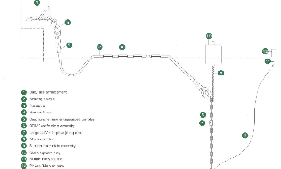
Typical mooring arrangement
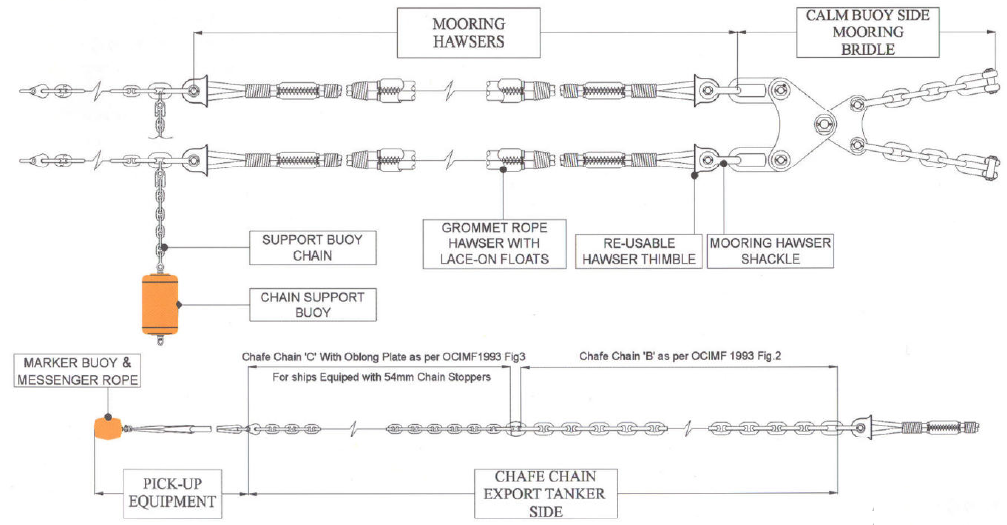
SPM MOORING ARRANGEMENT
